Adjustable roof ventilator base

a ventilator base and adjustable technology, applied in the field of roof ventilators, can solve the problems of reducing affecting the overall installation time, and affecting the efficiency of the insulation, so as to reduce the overall installation time, and reduce the effect of compromising

Active Publication Date: 2013-02-26
RAMSAY SERGE +1
View PDF15 Cites 2 Cited by
  • Summary
  • Abstract
  • Description
  • Claims
  • Application Information

AI Technical Summary

Benefits of technology

[0025]Accordingly, a main advantage of the present invention resides in that the roof ventilator base is designed to fit over the ridge of a conventional gable roof with the base being adjustable so as to be readily attached to existing roofs of the gable type construction.
[0026]Other advantages of the present invention include that the proposed structure allows for the connection of a roof-mounted air handler, such as a ventilator, to an air duct extending through roofs of various slopes or pitch. The proposed structure allows for angular adjustability through a set of quick and ergonomic steps without requiring special tooling or manual dexterity.
[0027]Also, the proposed structure allows for angular adjustment thereof prior to being installed on the roof, hence reducing the overall installation time.
[0028]Still furthermore, the proposed structure allows for angular adjustability with minimal compromise of the cross-sectional effective area through which the air is guided and with minimal flow obstruction and leakage. Yet, still furthermore, the proposed structure is designed so as to reduce the risks of leakage through its sections and so as to be manufacturable through conventional forms of manufacturing using a reduced number of components, hence providing a structure that will be economically feasible, long-lasting and relatively trouble-free in operation.
[0029]Also, the use of breakable segments instead of detachable sections greatly facilitates installation of the ventilator.

Problems solved by technology

One of the most common energy loss in a building is due to the heat transfer through the attic.
If the attic is allowed to become too warm, the installed insulation becomes ineffective and the attic heat is transferred to the living space below.
In colder climates, moisture builds up in the attic, sometimes significantly decreasing the efficiency of the insulation.
The moisture, regardless of its numerous potential origins, left unchecked will build up and potentially cause extensive damage within the structure.
Moisture originating from the shower, kitchen steam or the like not only potentially decreases the insulating value of insulation, but also potentially leads to mould and mildew growth.
As insulation improved, a point was reached where more insulation was not necessarily better or possible due to space limitations.
While this practice allows some of the heat to escape, the ventilation provided remains poor.
This also causes non-uniform heat distribution within the attic or roof structure.
Consequently, roof jack suppliers are faced with the problem of high costs and high storage space if they want to be able to supply roof jacks accommodating the full range of slopes and cross-sectional diameters encountered in the industry.
Even in cases wherein a given stock roof jack is available and used for a given roof pitch or slope, the slope of the roof may be slightly deviant from the design value and the stock roof jack may not fit the angle perfectly.
In such cases, the misfit may cause air leakage from the system or may cause the ventilator to be mounted at a slight angle which could, in turn, cause problems in operation of the ventilator.
The configuration of some prior art adjustable roof jacks sometimes unduly restricts the flow of air and / or creates air leaks.
Another main disadvantage associated with prior art structures is that they are typically not adapted to be used with so-called gable roofs.

Method used


Image

  • Adjustable roof ventilator base
  • Adjustable roof ventilator base
  • Adjustable roof ventilator base

Examples


Embodiment Construction

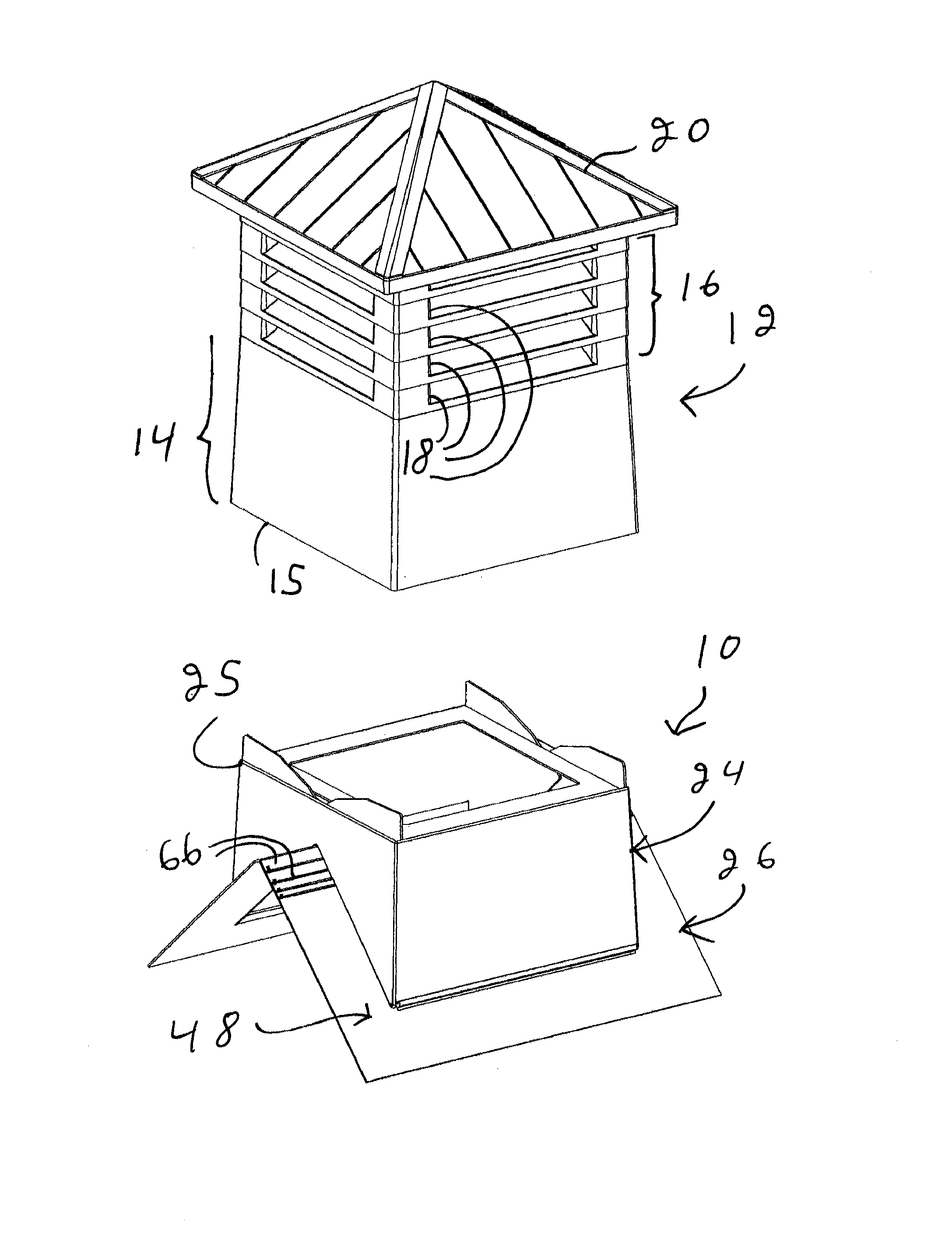
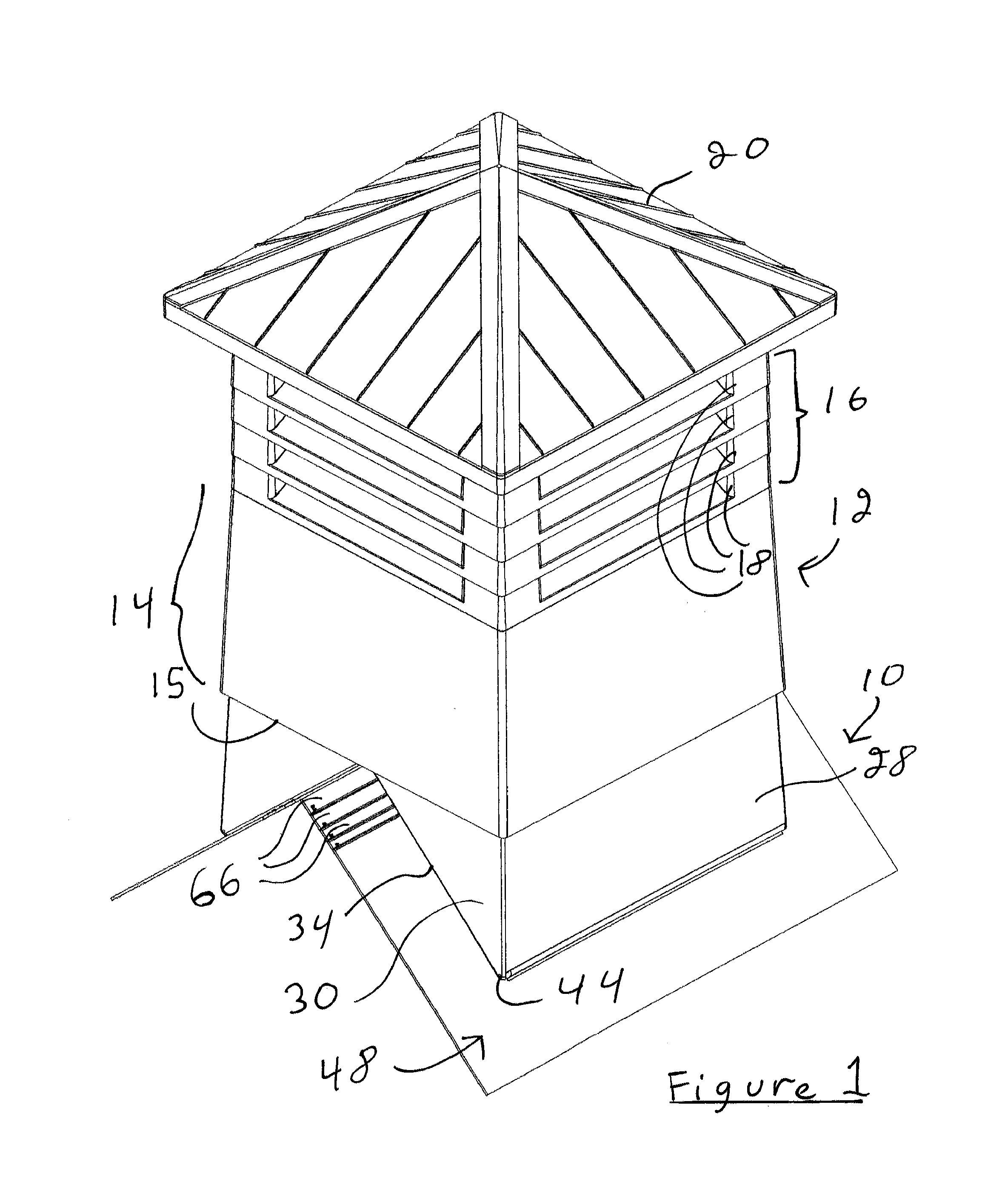
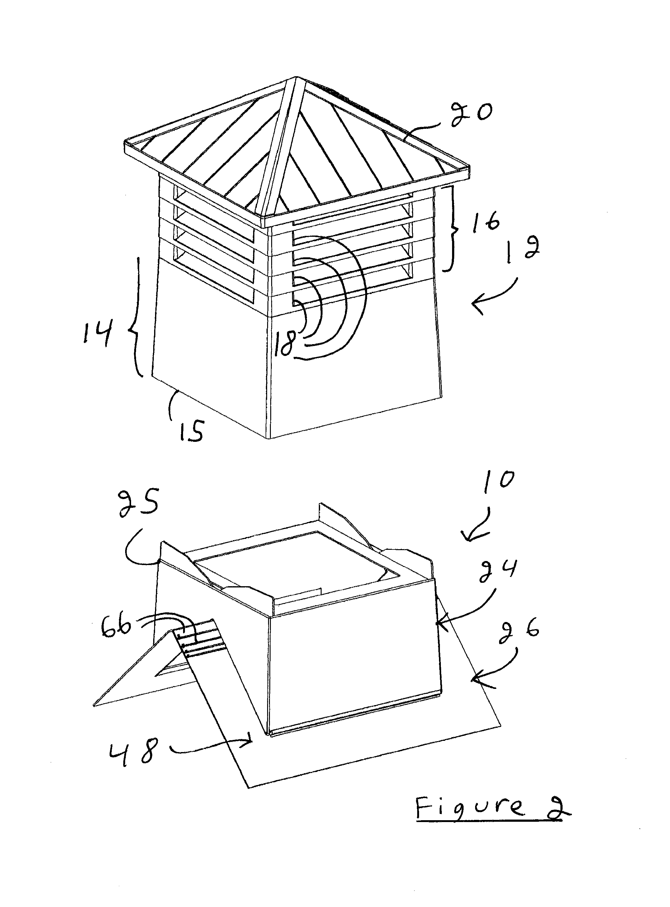
[0041]Referring to FIG. 1, there is shown an adjustable roof ventilator base in accordance with an embodiment of the present invention, generally indicated by the reference numeral 10. The roof ventilator base 10 is shown supporting a cupola 12. The cupola 12 is shown as having a cupola mounting section 14 defining a cupola lower peripheral edge 15 adapted to be abuttingly nested on the roof ventilator base 10. Typically, the cupola 12 also defines a venting section 16 provided with venting slots 18 and a cupola roof or dome 20.

[0042]It should however be understood that the roof ventilator base 10 could be used in other contexts, such as with other types of cupolas 20, other types of roof ventilator components, or the like, without departing from the scope of the present invention.

[0043]Referring now more specifically to FIGS. 9 through 13, there is shown that the roof ventilator base 10 is intended to be used on a gable-type roof 21, typically defining a pair of substantially symme...


PUM


Abstract

A roof ventilator mount for mounting a roof ventilator onto a gable-type roof (21), the roof ventilator including a roof ventilator base (10) defining a cupola mounting portion (25) for mounting a cupola (12) thereto, the roof ventilator mount comprising: a first mounting component (26), the first mounting component (26) including a first mounting plate (48) mountable to the roof (21); a second mounting component (26), the second mounting component (26) including a second mounting plate (48) mountable to the roof (21); the first and second mounting components (26) being mountable to the roof ventilator base (10) with proximal edges (47) thereof located substantially adjacent to each other and distal edges (49) thereof located spaced apart from each other; the first and second mounting plates (48) being each provided with a breakable segment (66) extending from the proximal edge (47), the breakable segment (66) being breakable from the remainder of the mounting plate (48) along a predetermined break line located at a predetermined distance from the distal edge (49).

Description

FIELD OF THE INVENTION[0001]The present invention relates to the general field of roof ventilators, and is particularly concerned with an adjustable roof ventilator base for allowing the roof ventilator to be mounted over the ridge of a gable roof.BACKGROUND[0002]Energy-efficiency is a serious consideration in building design and construction. Many building codes require builders to minimize energy requirements to maintain comfortable living spaces.[0003]One of the most common energy loss in a building is due to the heat transfer through the attic. In warm climates, heat builds up in the attic from solar energy incident on the roof or from heat transferred up from the living space. If the attic is allowed to become too warm, the installed insulation becomes ineffective and the attic heat is transferred to the living space below.[0004]In colder climates, moisture builds up in the attic, sometimes significantly decreasing the efficiency of the insulation. The moisture, regardless of i...

Claims


Application Information

Patent Timeline
Patent Type & Authority Patents(United States)
IPC IPC(8): F24F7/02E04B7/18
CPCE04D13/174F24F13/32F24F7/02
Inventor RAMSAY, SERGERAMSAY, LINDA
Owner RAMSAY SERGE
Why Eureka
Try Eureka