
Power plug with cable leakage protective function

a technology of leakage protection and power plugs, which is applied in the direction of connection contact materials, circuit breaking switches, coupling device connections, etc., can solve the problems of relatively more complicated internal structure and direct damage of household appliances, and achieves simple interior structure, reasonable design, and easy mass production

Active Publication Date: 2013-03-05
ZHONGSHAN KAPER ELECTRICAL
View PDF15 Cites 17 Cited by
  • Summary
  • Abstract
  • Description
  • Claims
  • Application Information

AI Technical Summary

Benefits of technology

The present invention is a power supply system for household appliances that has the following three technical effects: (1) it can protect the household appliance from inadvertent leakage failures when the appliance is in use and the leakage current reaches 4 to 6 millamps; (2) it can protect the household appliance from circuit breakages in the power supply live wire or neutral wire, and thus cut off the power supply to the appliance; and (3) it has a simple interior structure, a reasonable design, and is easy to mass-produce.

Problems solved by technology

Because the interior of such power plugs does not possess a leakage protection structure, pulling the pins out creates a leakage failure with a live wire, neutral wire, and ground wire; the live, neutral, and ground wires encounter a leaking fault, and a short-circuiting failure occurs between the live and neutral wires on the output terminal of the power plug, and the household appliance suffers direct damage.
There have already appeared a number of power plugs having leakage protection functions; despite the ability thereof to cut off the power supply when a failure occurs in order to act to protect the household appliance, these power plugs have at present a relatively more complicated internal structure, which is not suited for mass production, and thus there is a need to solve the above problems.

Method used


Image

  • Power plug with cable leakage protective function
  • Power plug with cable leakage protective function
  • Power plug with cable leakage protective function

Examples


Embodiment Construction

[0025]The following combines the drawings with an embodiment of the present invention to provide a more detailed description.

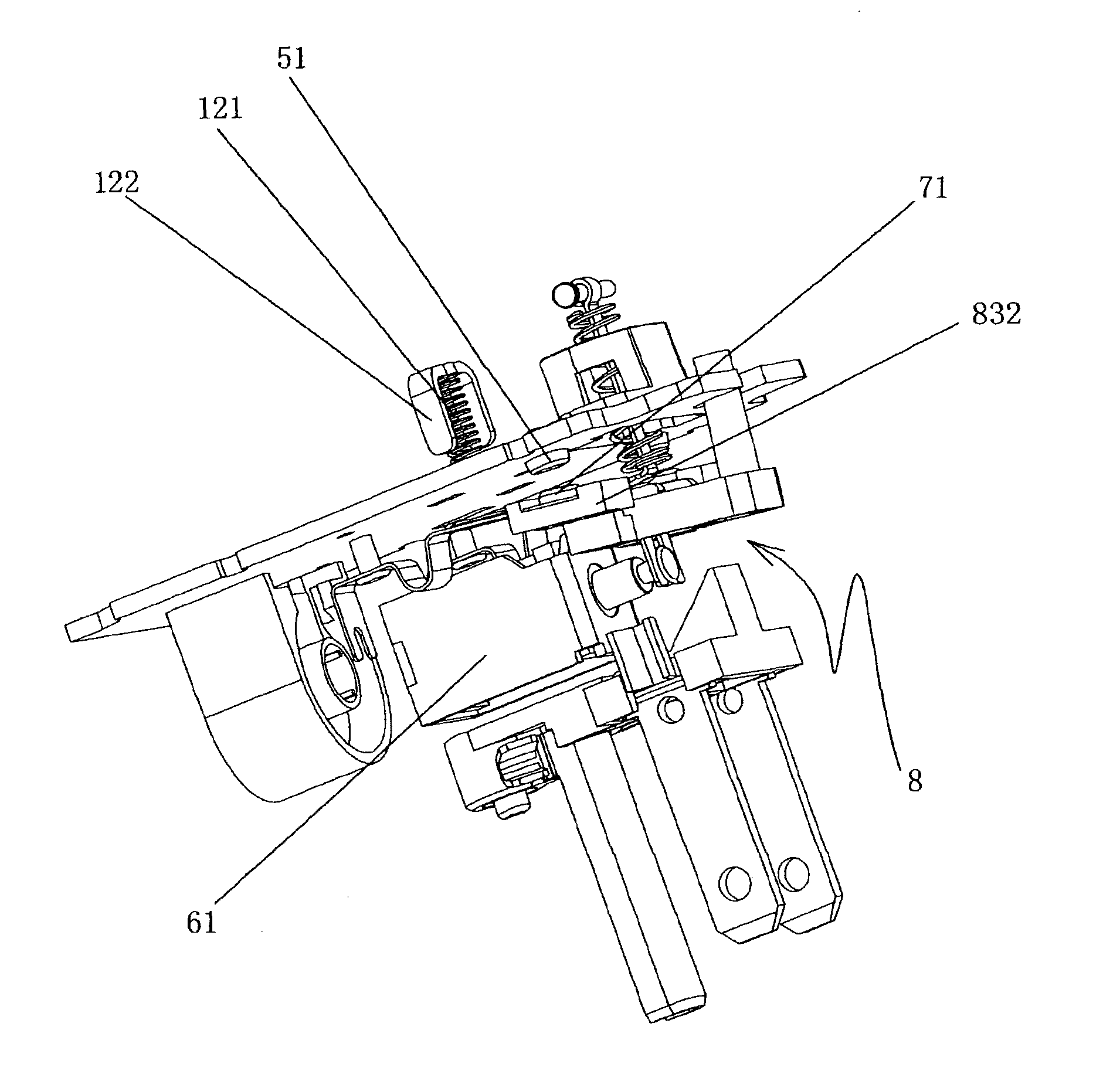
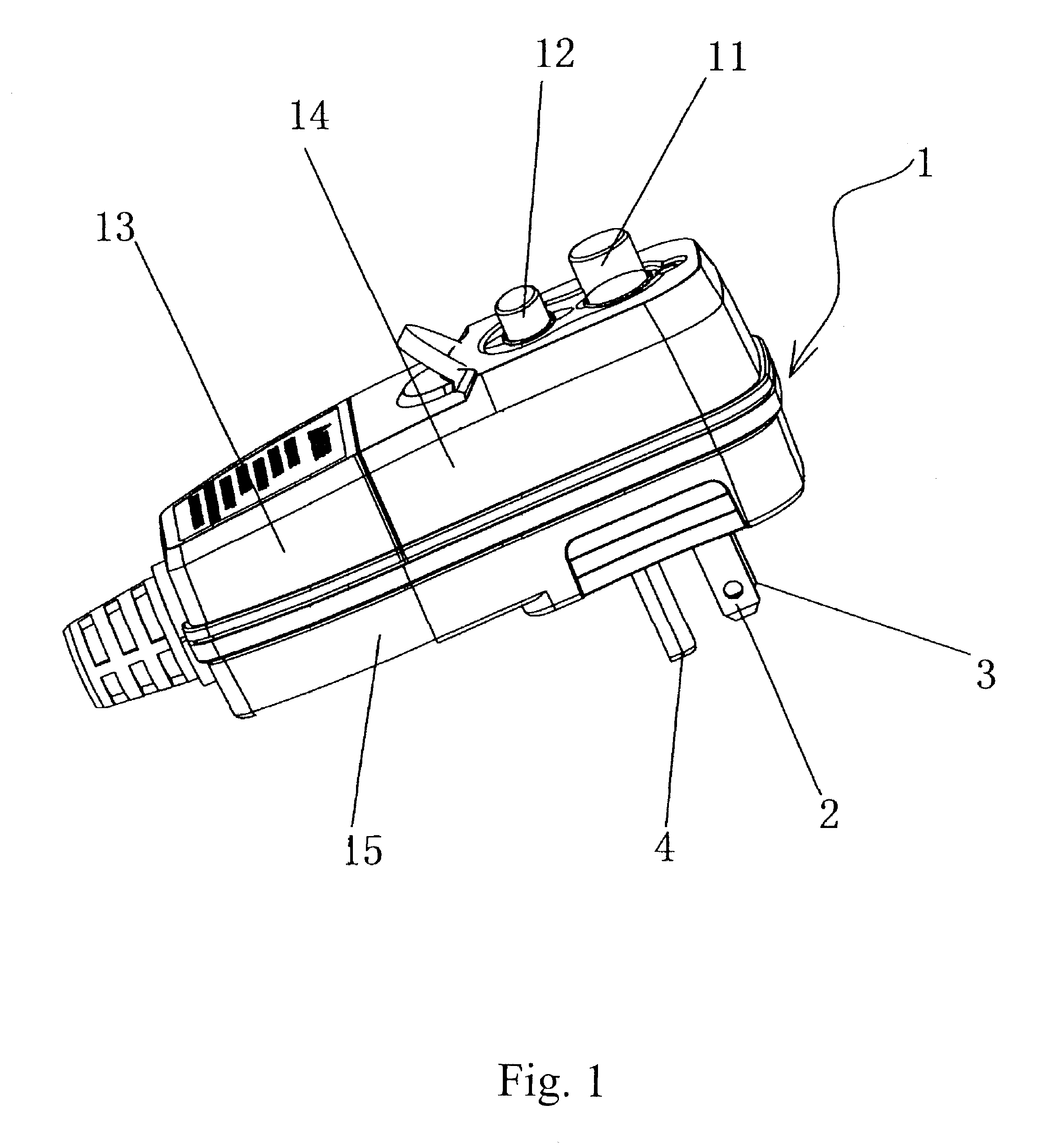
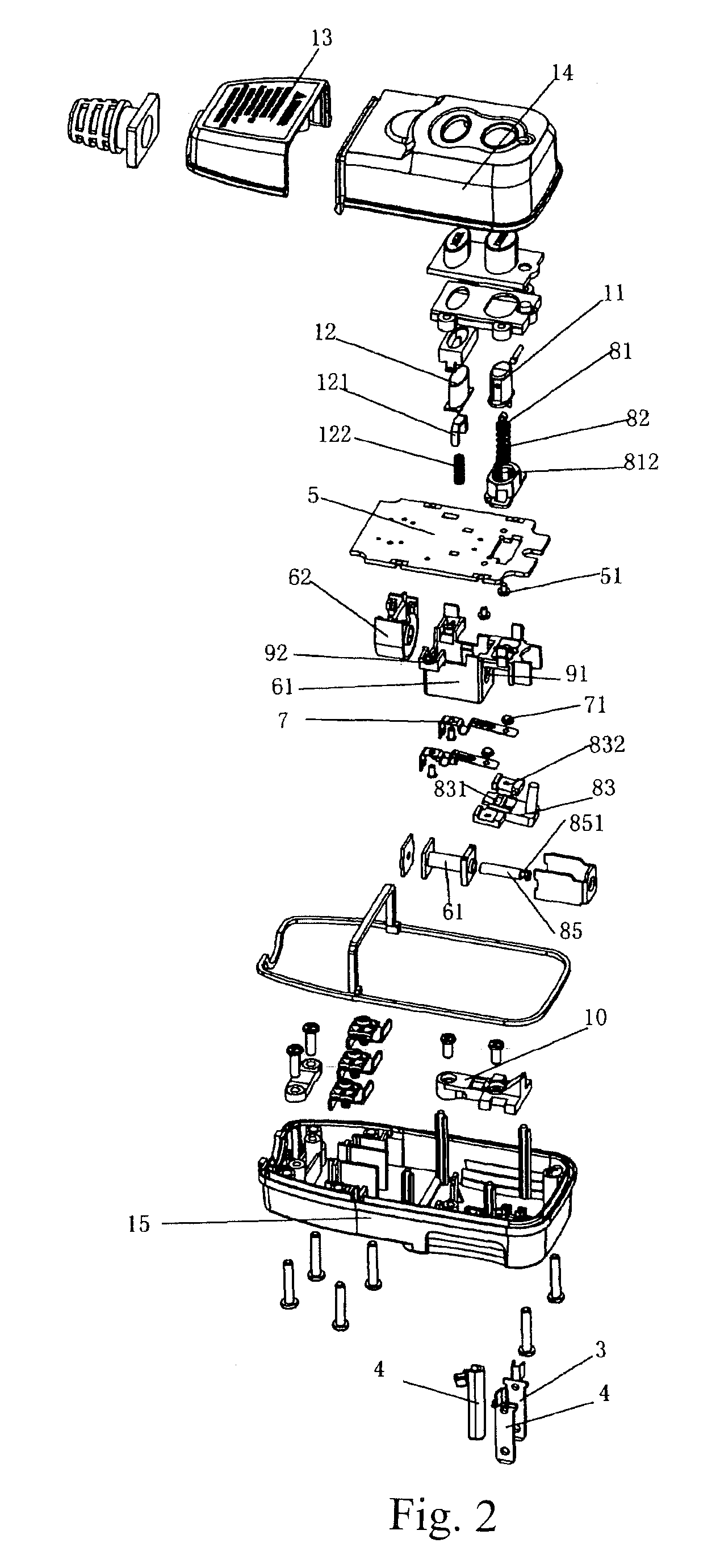
[0026]With reference to FIGS. 1 to 11, the present invention discloses a power plug having a leakage protection function, comprising a casing 1, a reset button 11 and a test button 12 being provided to the surface of the top of the casing 1; a power supply live wire pin 2, neutral wire pin 3, and ground wire pin 4 being provided to the bottom of the casing 1; a circuit board 5 being provided to the interior of the casing 1; and a leakage protection circuit for detecting a cable leakage failure on the output of the power source being provided onto the circuit board 5; wherein a pair of movable springs 7 for separate electrical connections with the power supply live wire plug 2 and the neutral wire plug 3 are fixedly provided to the bottom of the circuit board 5, movable contact points 71 of the separate electrical connections being on the free ends of the pair ...


PUM


Abstract

The present invention discloses a power plug providing leakage protection comprising a casing, reset button and test button provided to the surface of the top of the casing; wherein movable springs respectively connected to power supply live wire and neutral wire pins are fixedly provided to the bottom part of a circuit board, movable contact points have separate electrical connections with free ends of the movable springs, stationary contact points corresponding to the movable contact points are provided to the circuit board and connected to a loading power supply cable; and a tripping device capable of contacting or disconnecting the movable and stationary contact points is provided inside the casing. The present invention is safe; has strong protective performance, simple structure, and reasonable design, and is safe, suited for mass production, and able to detect a power cable leakage failure and promptly sever the loaded connection with the power supply.

Description

CROSS-REFERENCE TO RELATED APPLICATIONS[0001]The present application is a national phase entry under 35 U.S.C. §371 of International Application No. PCT / CN2010 / 000059, filed Jan. 13, 2010, published in Chinese, which claims priority from CN 200920057724.4, filed May 27, 2009, all of which are incorporated herein by reference.BACKGROUND OF THE INVENTION[0002]The present invention relates to a power plug having a leakage protection function, i.e., ground fault circuit interrupter (abbreviated as GFCI), and refers in particular to a power plug having a leakage protection function that is installed onto a household appliance such as an air conditioner, a refrigerator, or a television.[0003]At present, people connect household appliances to the utility power supply via power plugs; the majority of power plugs that are currently commercially available are structured so as to comprise a casing, two or three externally exposed pins and a power cable wire connected to the pins being installe...

Claims


Application Information

Patent Timeline
Patent Type & Authority Patents(United States)
IPC IPC(8): H01H3/14H01H83/02
CPCH01R13/7135H01H83/14
Inventor ZOU, BILL
Owner ZHONGSHAN KAPER ELECTRICAL
Learn More