
Production apparatus for electro-deposited metal foil, production method of thin plate insoluble metal electrode used in production apparatus for electro-deposited metal foil, and electro-deposited metal foil produced by using production apparatus for electro-deposited metal foil

a production apparatus and metal foil technology, applied in the production apparatus of electro-deposited metal foil, can solve the problems of affecting the polarization performance of electrolysis, difficult to produce electro-deposited copper foil with high quality in advanced technologies, and difficult to obtain a uniform alloy composition on the same surface of lead alloy electrodes, etc., to achieve excellent thickness uniformity and reduce the fluctuation of the thickness of the electro-deposited metal foil

Active Publication Date: 2013-03-12
DE NORA PERMELEC LTD
View PDF6 Cites 0 Cited by
  • Summary
  • Abstract
  • Description
  • Claims
  • Application Information

AI Technical Summary

Benefits of technology

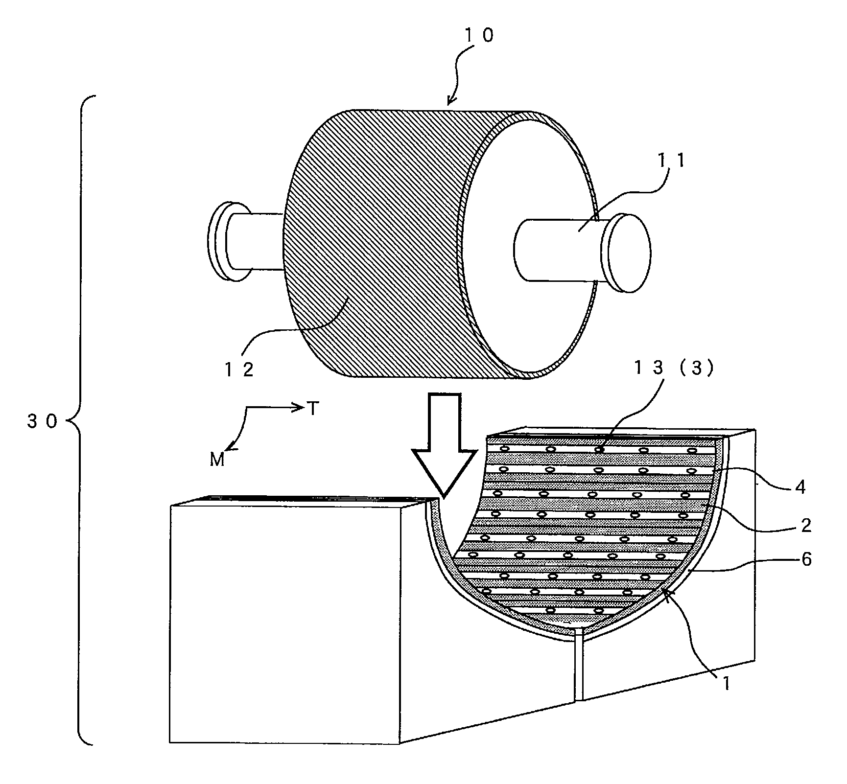
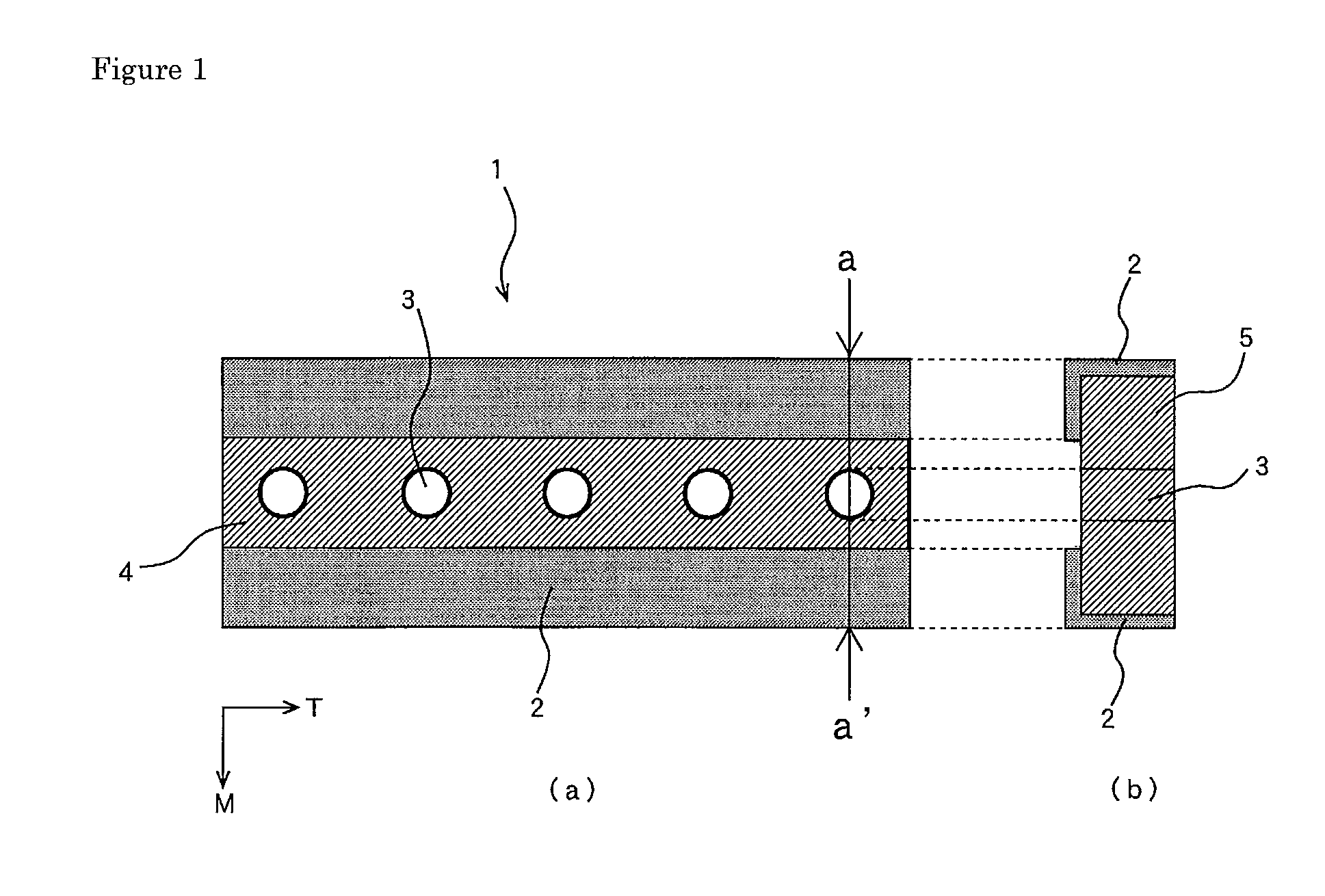
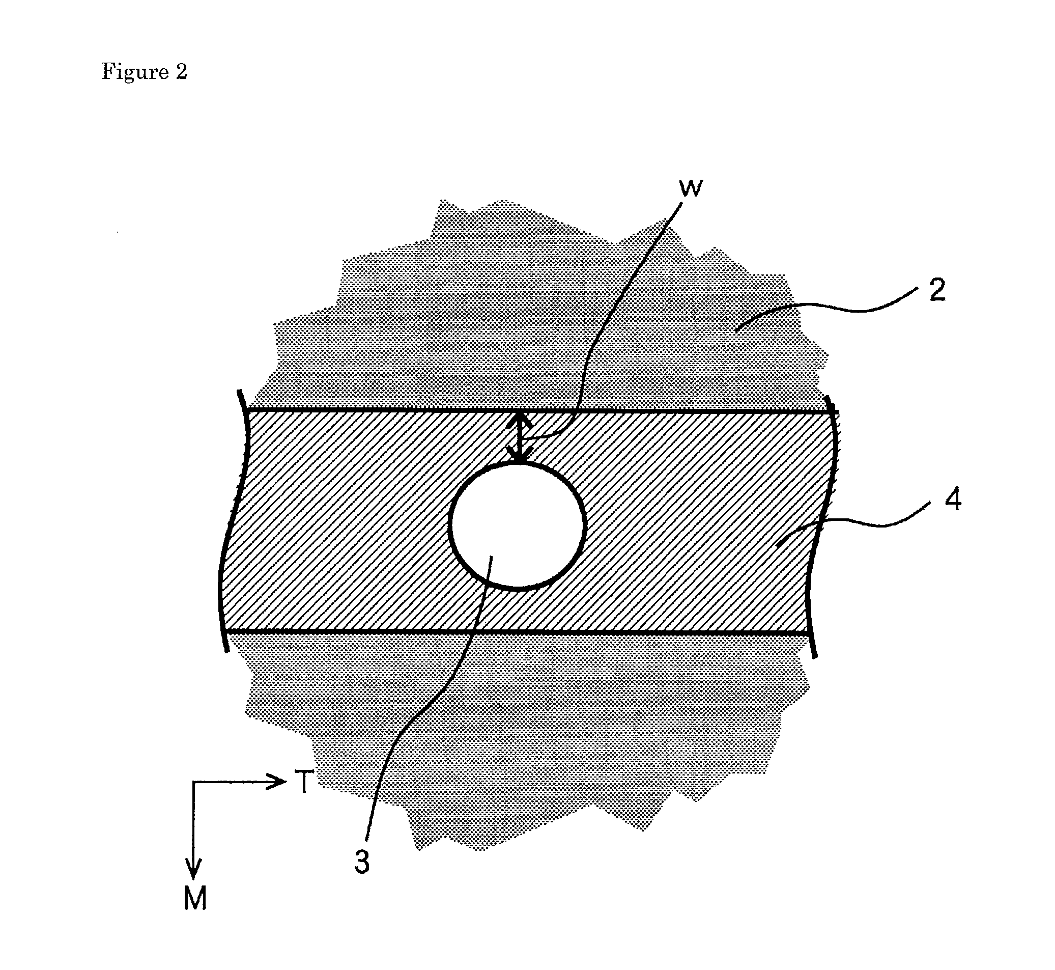
[0020]The production apparatus for electro-deposited metal foil according to the present invention comprises a special surface shape on the surface of the insoluble anode which is the conductive electrode material stripped belt provided in the conductive electrode material coating layer, and the shape can drastically reduce thickness fluctuation of the electro-deposited metal foil. To prevent generation of an abnormal electric current in electrolysis, a certain specified production method is used in the process to provide the conductive electrode material stripped belt in the conductive electrode material coating layer of the thin plate insoluble metal electrode that constitutes the insoluble anode. Thus, the electro-deposited metal foil produced by using the production apparatus for electro-deposited metal foil according to the present invention has excellent thickness uniformity that cannot be achieved in the conventional electro-deposited metal foil.

Problems solved by technology

However, with increasing size of the continuous electrolysis apparatus, it has been made difficult to obtain a uniform alloy composition in the same surface of the lead alloy electrode.
Also, for the lead alloy electrode in a sulfuric acid base solution used as an electrolytic solution, deviations in alloy composition, a difference in crystal structure and the like between lots drastically affect polarization performance in electrolysis, and it has been made difficult to produce electro-deposited copper foil having high quality in an advanced technologies.
In addition, the lead alloy electrode is consumed in electrolysis to result deformation of a shape of an electrode surface easily, and maintenance costs are increased.
They may cause various defects in products when contaminated in the electro-deposited copper foil.
However, even when the insoluble electrode structure disclosed in Japanese Patent Laid-Open No. 5-202498 is used in continuous production of electro-deposited metal foil; it could not always satisfy latest requirements for electro-deposited metal foil.

Method used


Image

  • Production apparatus for electro-deposited metal foil, production method of thin plate insoluble metal electrode used in production apparatus for electro-deposited metal foil, and electro-deposited metal foil produced by using production apparatus for electro-deposited metal foil
  • Production apparatus for electro-deposited metal foil, production method of thin plate insoluble metal electrode used in production apparatus for electro-deposited metal foil, and electro-deposited metal foil produced by using production apparatus for electro-deposited metal foil
  • Production apparatus for electro-deposited metal foil, production method of thin plate insoluble metal electrode used in production apparatus for electro-deposited metal foil, and electro-deposited metal foil produced by using production apparatus for electro-deposited metal foil

Examples


example

[0059]In the Example, a thin plate insoluble metal electrode 1 described below was prepared and used as the insoluble anode of the production apparatus for electro-deposited metal foil shown in FIG. 4, polarization and electrolysis was performed in a static state without rotating a rotating cathode drum to produce electro-deposited copper foil, and thickness fluctuation along a transverse direction was measured.

[0060]Production of thin plate insoluble metal electrode: In the production of the thin plate insoluble metal electrode 1 in the Example, the working process including Steps A to D shown in FIG. 5 was conducted. Each step will be described one by one.

[0061]Step A: A titanium plate having a length of 1.5 m, a width of 30 cm, and a thickness of 1 mm having a shape matching to the insoluble anode shape was prepared as a substrate 5.

[0062]Step B: The titanium plate was pretreated and activated. Meanwhile, iridium chloride and tantalum chloride were dissolved in diluted hydrochlor...


PUM

PropertyMeasurementUnit
widthaaaaaaaaaa
thicknessaaaaaaaaaa
thicknessaaaaaaaaaa

Abstract

An object of the present invention is to provide a production apparatus for electro-deposited metal foil or the like that can reduce thickness fluctuation of electro-deposited metal foil. To achieve the object, a production apparatus for electro-deposited metal foil or the like in which a cathode and an insoluble anode apart from each other, supplying an electrolytic solution through a gap between the cathode and the anode, making the cathode move along to the insoluble anode, electrodepositing a metal component on an electro-deposition surface of the moving cathode is applied. Wherein the insoluble anode is a thin plate insoluble metal electrode provided with a conductive electrode material coating layer on a surface of a substrate made of a corrosion-resistant material, and detachably mounted to an electrode base by using predetermined fixing means, and the conductive electrode material coating layer of the thin plate insoluble metal electrode is provided with a conductive electrode material stripped belt in a direction perpendicular to a moving direction of the cathode, and the fixing means is provided in the conductive electrode material stripped belt.

Description

TECHNICAL FIELD[0001]The present invention relates to a production apparatus for electro-deposited metal foil, a production method of a thin plate insoluble metal electrode used in the production apparatus for electro-deposited metal foil, and an electro-deposited metal foil produced by using the production apparatus for electro-deposited metal foil. More particularly, the present invention relates to a production apparatus suitable for producing an electro-deposited metal foil produced as a long sheet-like product by continuous electrolysis.BACKGROUND ART[0002]Conventionally, among a technology for producing metal foil by a continuous electrolysis method, production of an electro-deposited copper foil that is a basic material for producing a printed-wiring board has been a typical technology. For example, in the apparatus for a continuous electrolysis of electro-deposited copper foil, a drum (cylindrical) cathode and an anode such as a lead alloy electrode made of an insoluble lead...

Claims


Application Information

Patent Timeline
Patent Type & Authority Patents(United States)
IPC IPC(8): C25D17/10C25D17/12
CPCC25D1/04C25D7/0642C25D7/0692C25D1/08C25D1/00C25D17/14Y10T428/12431
Inventor OZAKI, YUSUKEKUNIMATSU, AKIRA
Owner DE NORA PERMELEC LTD
Learn More