
Noise rejection and parasitic capacitance removal implementations

a capacitance removal and capacitance rejection technology, applied in the direction of pulse technique, instrumentation, program control, etc., can solve the problems of difficult combat, easy adverse effects of noise in the capacitive sensing circuit used to detect touch or proximity events, and noise generated by appliances such as electric drills and mobile phones, so as to reduce noise coupling

Active Publication Date: 2013-03-12
AZOTEQ HLDG LTD
View PDF50 Cites 22 Cited by
  • Summary
  • Abstract
  • Description
  • Claims
  • Application Information

AI Technical Summary

Benefits of technology

The invention provides a way to continuously monitor noise in a capacitive sensing circuit. This allows for accurate identification and removal of individual samples affected by noise. Additionally, the invention reduces the effective capacitance of a sense plate by removing a value charge from a reference capacitor during each charge transfer cycle. This results in a noise alarm with minimal impact on the measurements.

Problems solved by technology

A capacitive sensing circuit used to detect touch or proximity events is easily adversely affected by noise.
Appliances such as electric drills and mobile phones generate noise which is difficult to combat.
The effect of noise on apparatus such as an oven, a cooking plate, a chain saw or the like, which is designed to be controlled by the use of capacitive sensing switches, responsive to touch or proximity, is unacceptable.
The false detection of a touch or proximity event could have serious adverse consequences and this, in itself, limits or prevents the adoption of capacitive sensing arrangements in many applications.
This leads to the conclusion that a product which may work satisfactorily under certain conditions can be adversely affected at other times.

Method used


Image

  • Noise rejection and parasitic capacitance removal implementations
  • Noise rejection and parasitic capacitance removal implementations
  • Noise rejection and parasitic capacitance removal implementations

Examples


Embodiment Construction

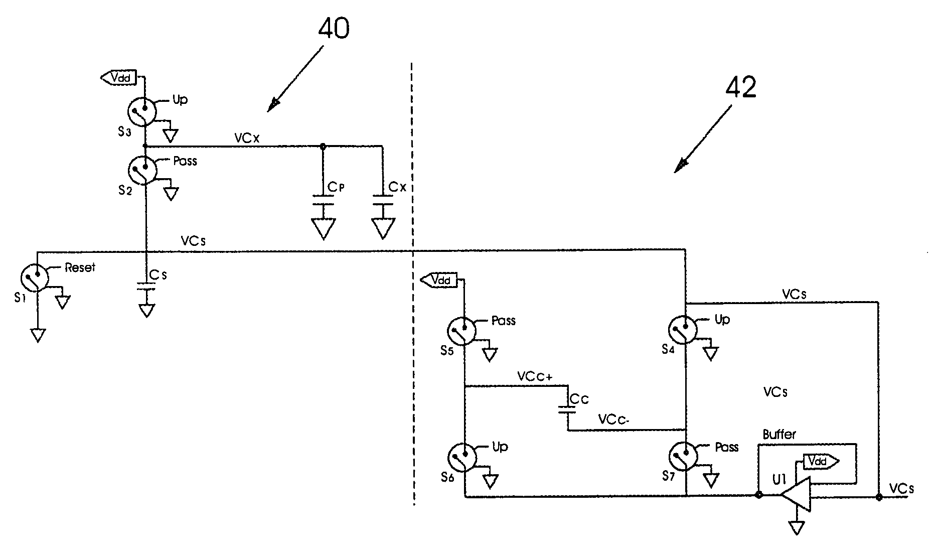
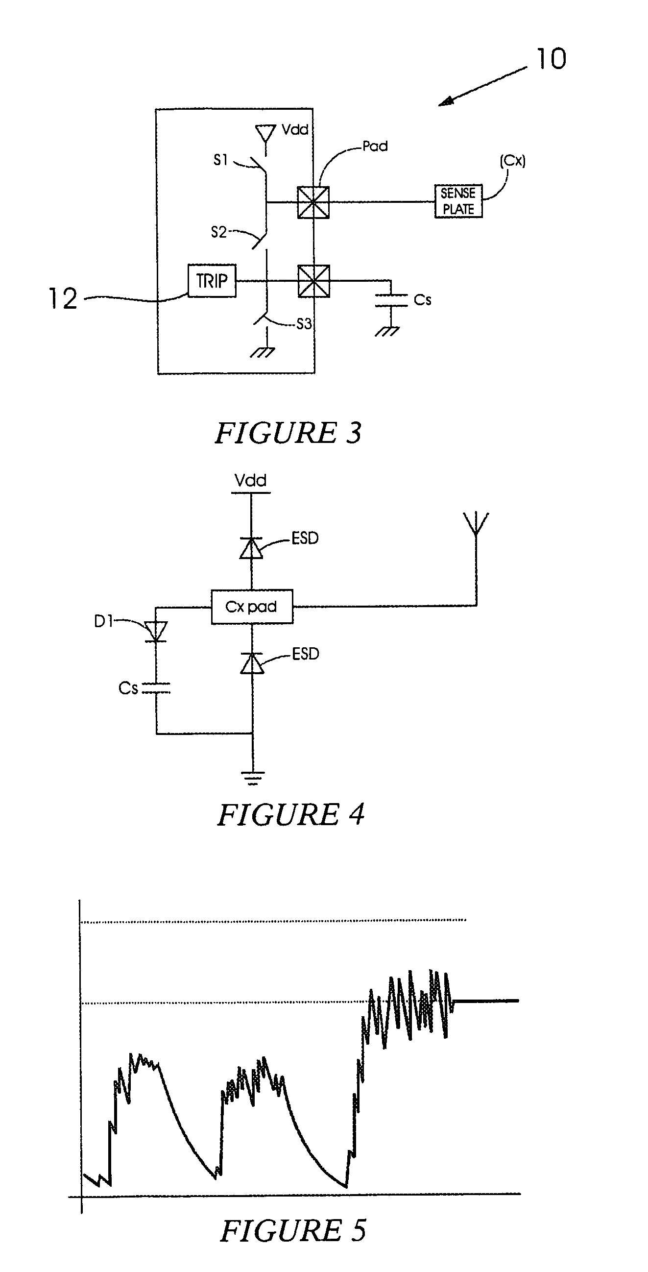
[0035]In a capacitive sensing circuit a sense plate or element, designated in this specification by the reference Cx, is charged to a working voltage. A touch or proximity event is reflected by a change in capacitive coupling to the sense plate and a resulting change (delta) in the charge on the sense plate that can be detected when the sense plate is discharged into a reference capacitor.

[0036]In general terms use is made of a charge transfer principle to measure the capacitive coupling of the sense plate to the environment. When an object approaches the sense plate the capacitive coupling to the environment changes, typically increasing the capacitance of the plate, and this change is detected by the circuit which then interprets the change as a proximity or touch event.

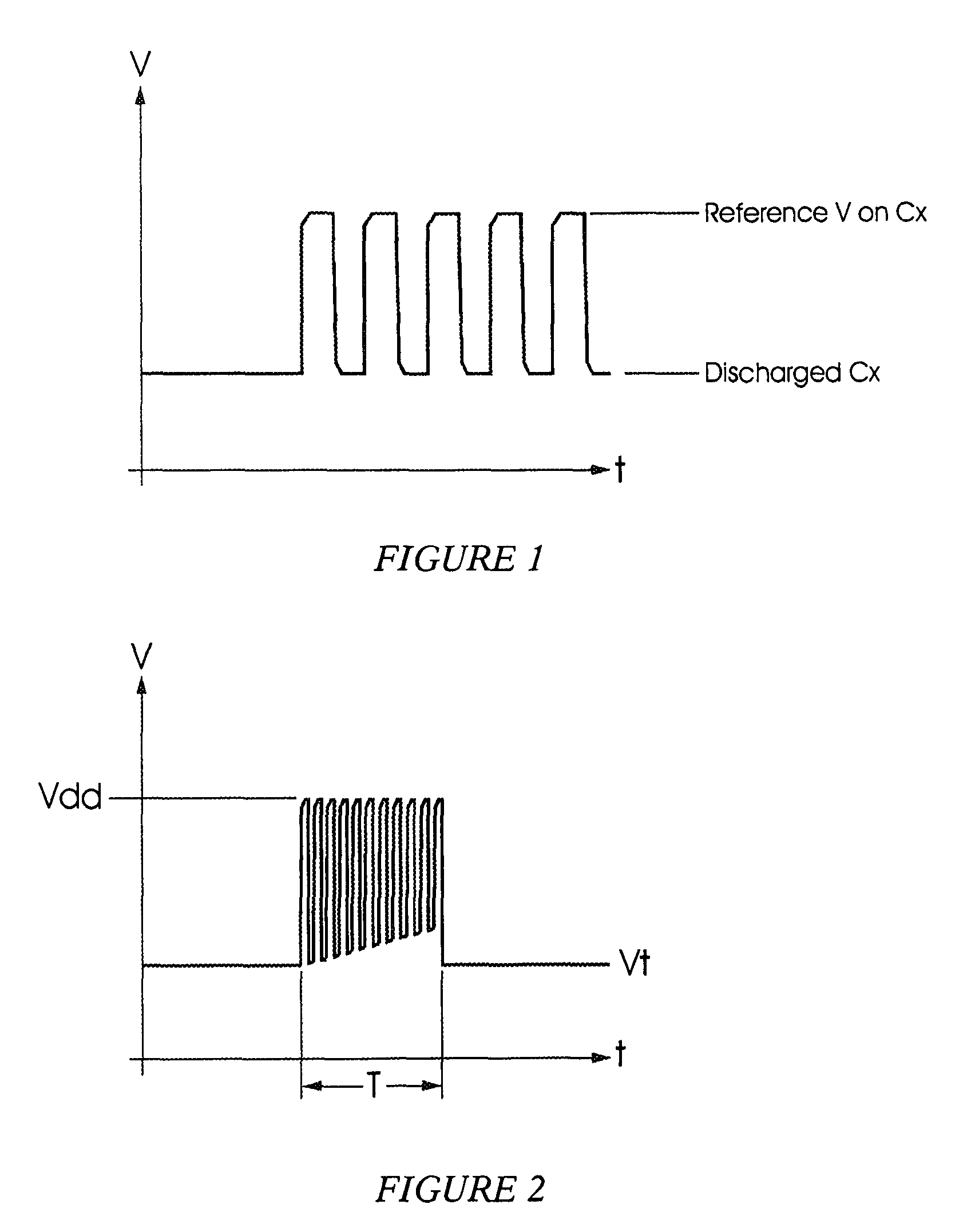
[0037]FIG. 1 of the accompanying drawings illustrates initial waveforms on a sense plate Cx as the sense plate is charged from a discharged state to a voltage level which is stable over time, particularly on a shor...


PUM


Abstract

A capacitive sensing circuit including a microchip and a sense plate, wherein the microchip comprises a hardware Q RF noise detector module that provides a logical indication of when noise impacts on the integrated circuit.

Description

BACKGROUND OF THE INVENTION[0001]This invention relates to the rejection or detection of noise in a capacitive sensing circuit and reduction of sense plate capacitance or parasitic capacitance.[0002]A capacitive sensing circuit used to detect touch or proximity events is easily adversely affected by noise. This problem is normally addressed by trying to adjust a de-bouncing circuit and filtering and voltage trip levels.[0003]Appliances such as electric drills and mobile phones generate noise which is difficult to combat. The effect of noise on apparatus such as an oven, a cooking plate, a chain saw or the like, which is designed to be controlled by the use of capacitive sensing switches, responsive to touch or proximity, is unacceptable. The false detection of a touch or proximity event could have serious adverse consequences and this, in itself, limits or prevents the adoption of capacitive sensing arrangements in many applications.[0004]Most people are aware from personal experien...

Claims


Application Information

Patent Timeline
Patent Type & Authority Patents(United States)
IPC IPC(8): G01R27/26
CPCH03K17/16H03K17/955
Inventor BRUWERVILJOEN, JEANHARKER, GRANT CECILVAN DER MERWE, DOUW GERBRANDT
Owner AZOTEQ HLDG LTD
Learn More