Power tool

a technology of power tools and tools, applied in the field of power tools, can solve the problems of transmission vibrations dominating the vibrations, and achieve the effect of reducing the vibrations occurring in operation and preventing lateral deviation of the tool members

Active Publication Date: 2013-03-19
ANDREAS STIHL AG & CO KG
View PDF23 Cites 16 Cited by
  • Summary
  • Abstract
  • Description
  • Claims
  • Application Information

AI Technical Summary

Benefits of technology

[0004]It is an object of the present invention to provide a power tool of the aforementioned kind in which the vibrations that result in operation are reduced.
[0007]In order to reduce the transmission forces of first and second order and thus also the resulting vibrations, it is now proposed to orient the two connecting rods in opposite directions relative to one another. The pivot joint of the first connecting rod is thus arranged on the end of the first connecting rod that is facing the tool members and the pivot joint of the second connecting rod is positioned on the opposite end of the second connecting rod that is facing away from the tool members. As a result of the opposite orientation of the two connecting rods the forces which are introduced in operation by the oscillating tool member masses, in particular the mass forces of the second order, are substantially and in particular completely compensated or canceled. In this way, the vibrations that occur in operation in particular at high engine speed can be significantly reduced. The arrangement of the pivot joint at the second connecting rod on the end of the second connecting rod that is facing away from the tool members can be realized in a constructively simple way. The required mounting space is only minimally enlarged. Thus, in a simple way the vibrations occurring in operation can be reduced and the service life of the power tool can be increased.
[0008]A simple configuration results when the connecting rods each are arranged on an eccentric cam wherein the eccentric cams are rotatingly driven about a common axis of rotation. In this connection, the two eccentric cams are advantageously arranged on a drive disk that in particular is rotatingly driven by a pinion about the axis of rotation. The drive disk together with the two eccentric cams can be configured as a monolithic part so that only one component is required for driving of the connecting rods. The two eccentric cams are advantageously arranged on opposite faces of the drive disk. In this way, each connecting rod is resting on the drive disk. This reduces the relative movements during operation and thus the resulting forces. However, it can also be advantageous to arrange both connecting rods on one face or side of the drive disk so that the connecting rods rest on one another.
[0010]Advantageously, the linkage rod at the second pivot joint is guided in a direction parallel to the movement direction of the second tool member, in particular along an extension of the longitudinal center axis of the second tool member. Because the first pivot joint and the second pivot joint are guided in the same plane, which advantageously also contains the axis of rotation of the drive disk, and because the two connecting rods at any point in time are arranged parallel to one another, the forces of second order that are generated in operation in the transmission cancel one another completely. The linkage rod produces additional excitation forces of the first order. Advantageously, on the first tool member an additional mass is arranged that compensates the mass forces that are caused by the linkage rod at least partially and in particular completely. In this way, the mass forces of first and second order can be compensated completely. In this way, a significant reduction of the vibrations occurring in operation is achieved. The additional mass can be attached to the first tool member or can be monolithically and integrally formed with the first tool member.
[0011]Advantageously, the tool members are guided by guide means in the movement direction. A lateral deviation of the tool members can thus be prevented in a simple way. The tool members project advantageously in the same direction and are arranged approximately on top one another. The two tool members can be arranged to be immediately stacked on one another or with intermediate positioning of additional elements. The tool members are in particular cutter bars and the power tool is advantageously a hand-held hedge trimmer.

Problems solved by technology

In particular, at higher engine speeds the transmission vibrations dominate the vibrations generated by the drive motor.

Method used


Image

  • Power tool
  • Power tool
  • Power tool

Examples


Embodiment Construction

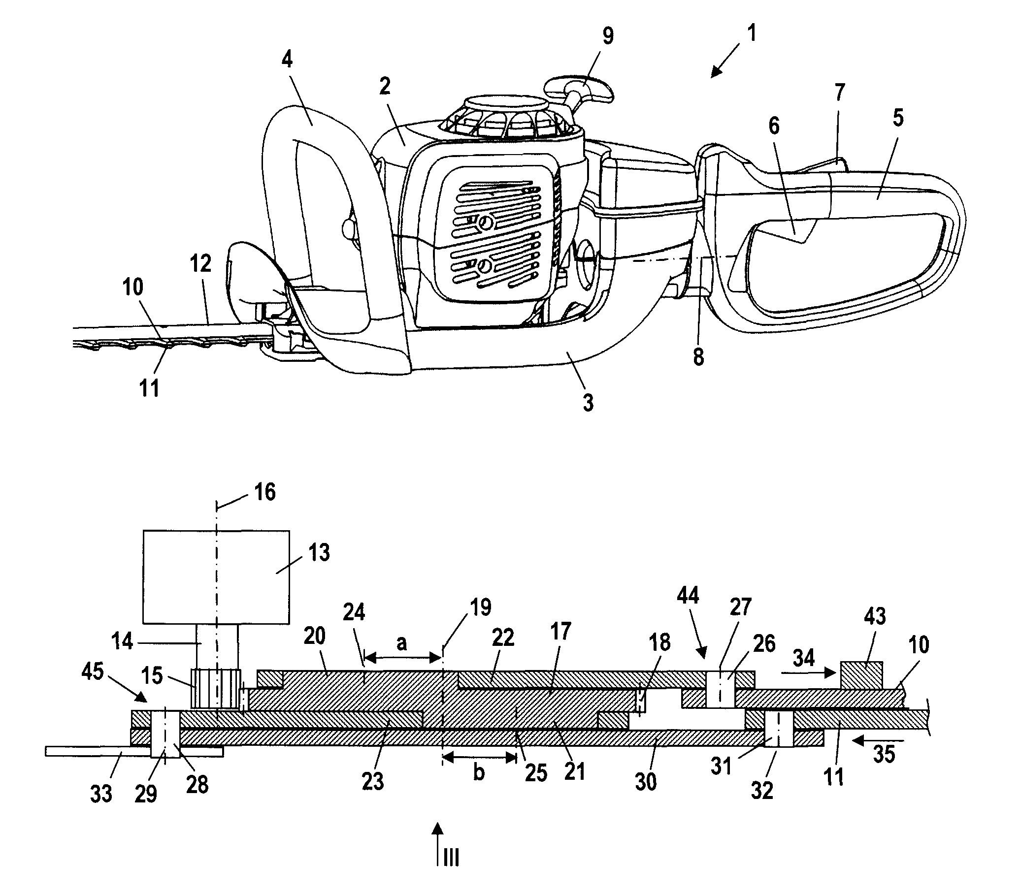
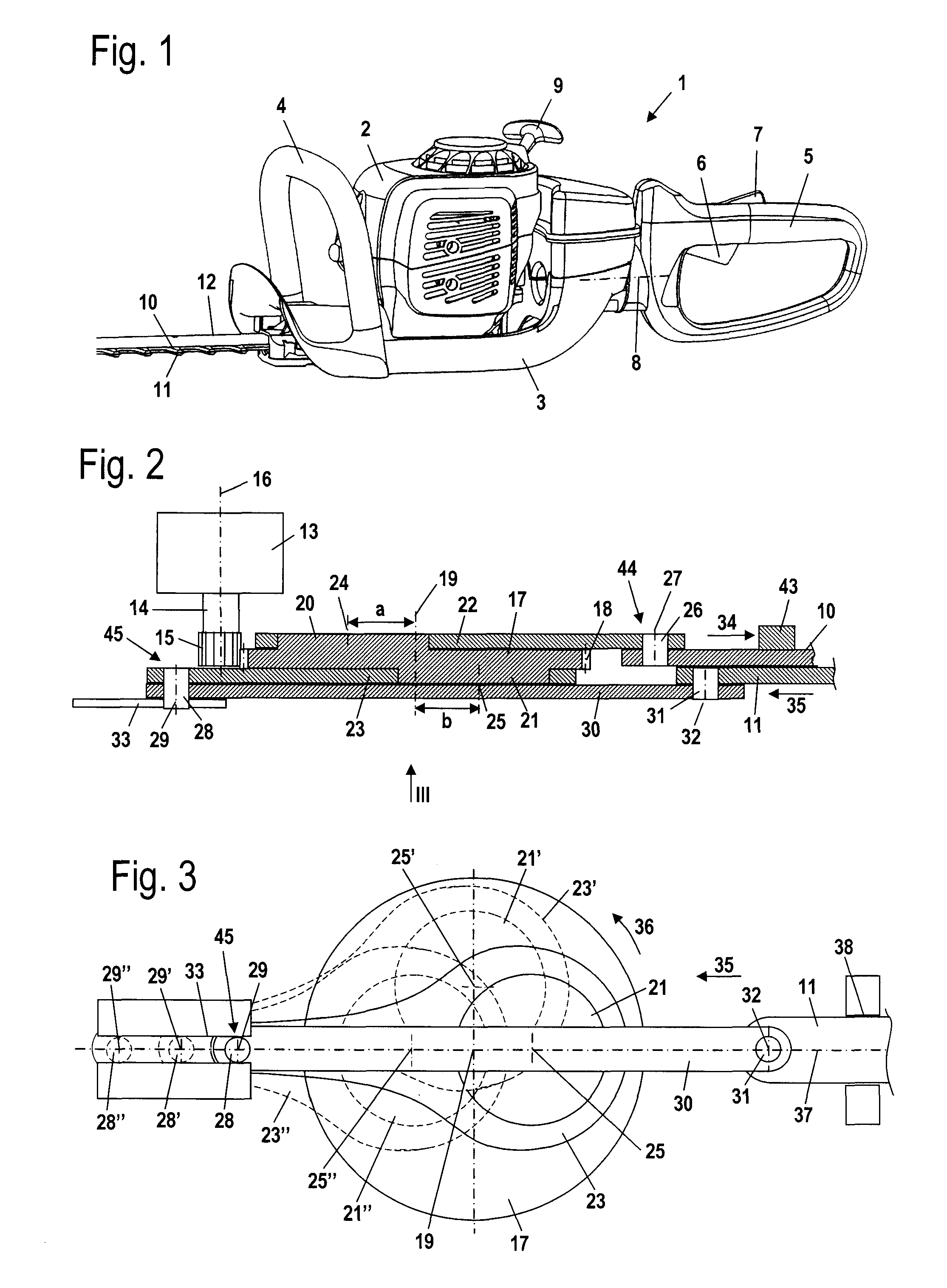
[0022]The embodiment of the power tool illustrated in FIG. 1 is a hand-held hedge trimmer 1. The power tool can also be, for example, a harvesting machine or another type of cutting device. For example, the power tool can be a combine harvester or a saw with oppositely driven cutting blades. The power tool can also be a special type of harvester such an olive shaker / harvester or the like. The hedge trimmer 1 has a housing 2 in which a drive motor, not shown in FIG. 1, is arranged. The drive motor is embodied as an internal combustion engine and is to be started by means of a starter handle 9 projecting from the housing 2. The housing 2 is supported by means of vibration damping elements on a grip frame 3. The grip frame 3 has a front handle 4 embodied as a bow-shaped handle as well as a rear handle 5. On the rear handle 5 a throttle lever 6 and a throttle lock 7 are pivotably supported. The rear handle 5 is supported so as to swivel about an axis of rotation 8 on the frame 3 so that...


PUM


Abstract

A power tool has a drive motor and first and second tool members driven reciprocatingly by the drive motor in opposite directions, respectively. The first tool member is driven by a first connecting rod and the first connecting rod is connected to the first tool member by a first pivot joint arranged on the first connecting rod. The second tool member is driven by a second connecting rod and the second connecting rod is connected to the second tool member by a second pivot joint arranged on the second connecting rod. The first pivot joint is arranged on an end of the first connecting rod which end is facing the tool members. The second pivot joint is arranged on an end of the second connecting rod which end is facing away from the tool members.

Description

BACKGROUND OF THE INVENTION[0001]The invention relates to a power tool, in particular a hand-held power tool such as a hedge trimmer or the like, comprising at least two tool members that are driven in a reciprocating fashion by a drive motor in opposite directions, respectively. Each tool member is driven by a connecting rod that is connected to the correlated tool member by means of a pivot joint arranged on the connecting rod. The pivot joint is arranged on the first connecting rod on the end of the first connecting rod that is facing the tool members.[0002]U.S. Pat. No. 5,771,583 discloses a power tool with a hedge trimmer attachment that has two oppositely driven shearing blades. The shearing blades are connected by connecting rods to an eccentric member. Both connecting rods extend in the direction toward the shearing blade supports, i.e., in the same direction.[0003]In power tools, in particular hand-held power tools, such as hedge trimmers or the like, the vibrations that oc...

Claims


Application Information

Patent Timeline
Patent Type & Authority Patents(United States)
IPC IPC(8): B26B19/02
CPCA01G3/053
Inventor GEROMILLER, LUDWIG
Owner ANDREAS STIHL AG & CO KG
Why Eureka
Try Eureka