Bias measurement for MEMS gyroscopes and accelerometers

a technology of accelerometer and bias measurement, which is applied in the direction of acceleration measurement using interia force, turn-sensitive devices, instruments, etc., can solve the problems of bias drift, time-consuming and expensive testing, and relatively sensitiveness of mems inertial instruments, so as to reduce the size and complexity of the imu and eliminate bias drift.

Inactive Publication Date: 2013-03-19
MILLI SENSOR & ACTUATOR SYST
View PDF8 Cites 13 Cited by
  • Summary
  • Abstract
  • Description
  • Claims
  • Application Information

AI Technical Summary

Benefits of technology

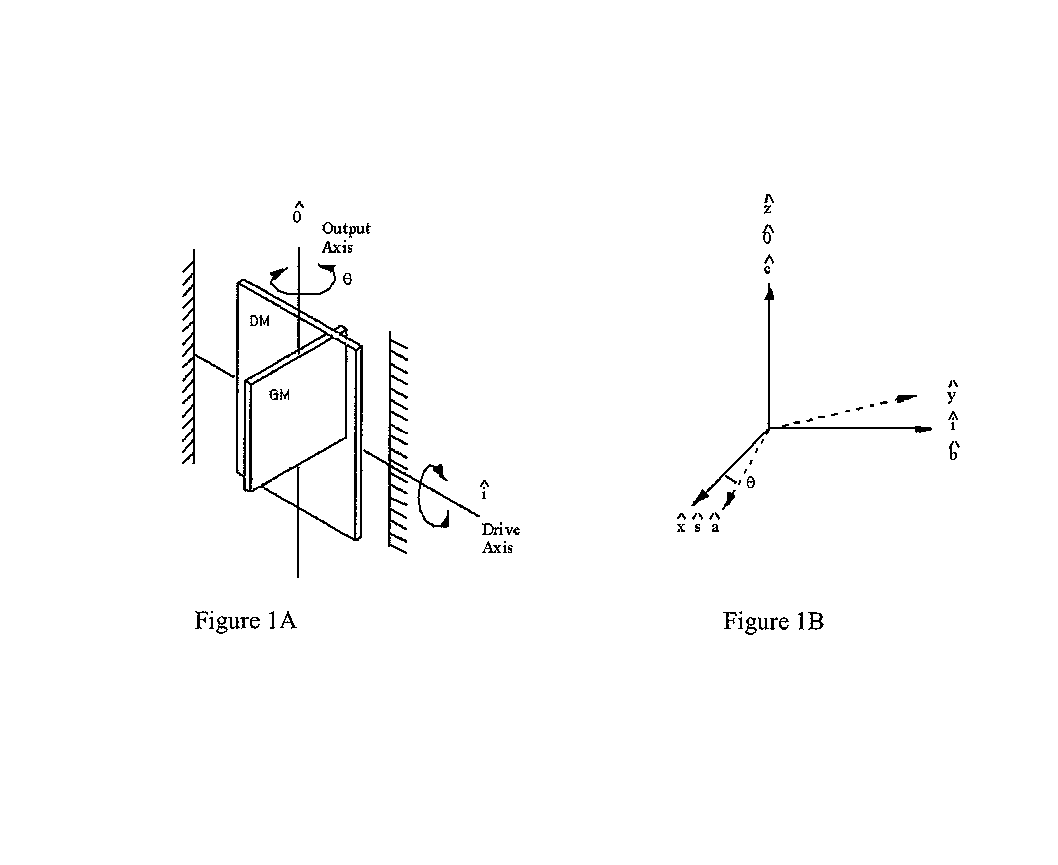
[0007]The G2-Gyroscope is a Coriolis gyroscope where the drive and output sense motions are angular oscillations. Its structure is generally planar and composed of two members: a Gyro Member and a Drive Member. The Gyro Member is the gyro. The Drive Member supports the Gyro Member above the substrate and is used to oscillate the Gyro Member about the Drive Axis, without applying direct actuation to the Gyro Member. Under rotation rate input, the Gyro Member responds by oscillating about the Output Axis (orthogonal to the Drive Axis). The Input Axis and Drive Axis are orthogonal to each other and lie in the plane of the gyroscope. The Output Axis is aligned normal to the plane. An attribute of this design is that the Gyro Member can be made symmetric about the Output Axis and therefore reduce sensitivity to cross-axis rotation rate inputs. By using the Drive Member to indirectly drive the Gyro Member, error torques are minimized.
[0012]This invention further relates to the indirect drive of the Gyro Member through a Drive Member (DM), to which the Gyro Member is attached. The purpose is to minimize unwanted drive of the Gyro Member about the Output Axis (quadrature source).
[0014]This invention also relates to the alternate design where the Gyro Member is larger and driven directly to oscillate about the Drive Axis. The larger size of the Gyro Member increases gyroscope sensitivity. In this case, the member that supports the gyro member relative to the substrate is not driven, and thus is not really a “Drive Member.” This member may thus be generally termed, for both preferred embodiments, a “support member.”
[0019]The phase sensitive detection method becomes more efficient at higher rates.
[0036]The invention also relates to the use of one in-plane gyroscope to measure Input Rotation Rates about both in-plane Body Axes. The use of the same gyroscope to measure both Input Rates reduces a source of error between the rates of the two Body Axes.
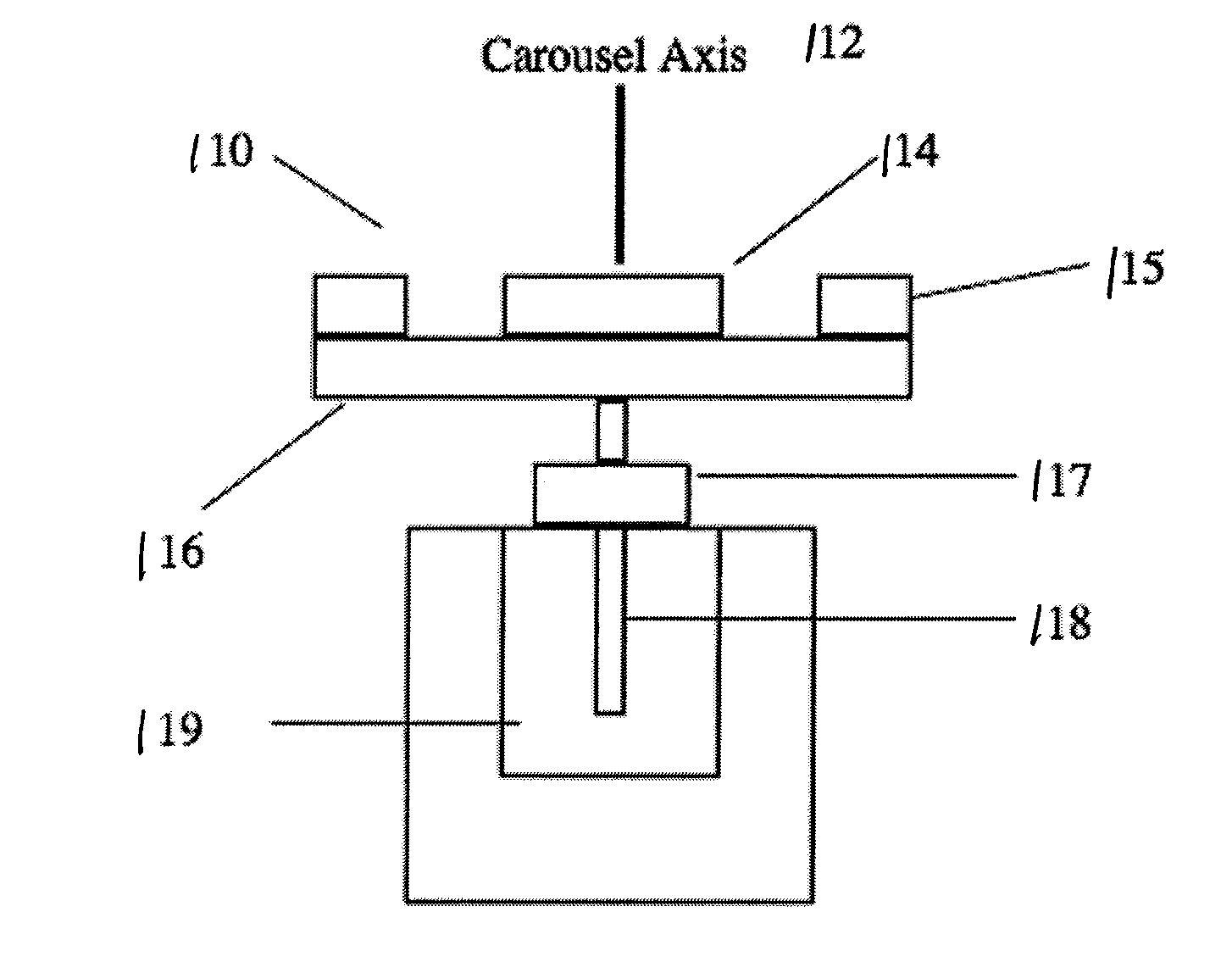
[0042]The invention also relates to the combination of carousel rotation and the phase-sensitive detection method to eliminate bias drift and 1 / f bias instability from the gyro and accelerometer signals. And because of carousel rotation, the IMU requires one in-plane gyro and one in-plane accelerometer as well as the Z-instruments, which reduces the size and complexity of the IMU.

Problems solved by technology

Due to their very small size, and materials and methods of construction, such MEMS inertial instruments are relatively sensitive to ambient temperature and other environmental factors.
These sensitivities makes them relatively unstable.
This testing is time consuming and expensive, and also may not anticipate every possible condition that the instrument may be exposed to, which can lead to errors.
Random components can be traced to a cause but cannot be controlled.
The problem is that under motion, the instrument bias is undistinguishable from the signal generated by the motion, hence the output in incorrect and the MEMS instrument is impractical and requires continuous correction to be useful.

Method used


Image

  • Bias measurement for MEMS gyroscopes and accelerometers
  • Bias measurement for MEMS gyroscopes and accelerometers
  • Bias measurement for MEMS gyroscopes and accelerometers

Examples


Embodiment Construction

[0129]The G2-Out Gyroscope 70, FIGS. 8 and 9, is a variation on the G2-Gyroscope where the Gyro Member 80 is the structural outer member, and the Gyro Member is driven directly about the Drive Axis 84. The Output Axis is still normal to the plane. The alignments of the Drive Axis and Input Axis 85 are as specified with the G2 Gyroscope.

Mechanical Design of the G2-Out Gyroscope

[0130]The mechanical design of the G2-Out gyro embodiment of the invention is described with FIG. 8. The gyro is mounted to the Pyrex substrate 71 via the mounting post 72 in the center. Ring structure 73 is attached to central post 72 with four radial flexures 74. The radial flexures allow oscillation of the gyro about the Output Axis (normal to the plane). From the ring is attached the rotor 75 of the capacitive rotary comb sensor. The fingers of the rotor extend radially towards the center of rotation. Four radial comb stators 76, 77, 78, 79 are mounted to the Pyrex substrate. The fingers of each stator exte...


PUM


Abstract

A system and method for separating bias instability of MEMS inertial instruments such as gyroscopes or accelerometers from the instrument signal, in which the inertial measurement instrument has an input axis and an output signal, and the bias instability has a frequency. The instrument is rotated about a rotation axis that is orthogonal to the input axis, at a frequency that is greater than the bias instability frequency. The instrument output signal is detected, and demodulated with a phase-sensitive detection method referenced to the instrument rotation.

Description

CROSS REFERENCE TO RELATED APPLICATION[0001]This application is a continuation in part of application Ser. No. 11 / 426,368 filed on Jun. 26, 2006 now U.S. Pat. No. 7,406,867, the disclosure of which is incorporated herein by reference. This application claims priority of Provisional application Ser. No. 60 / 745,438, with a filing date of Apr. 24, 2006, the disclosure of which is incorporated herein by reference.STATEMENT REGARDING FEDERALLY SPONSORED RESEARCH[0002]This invention was made with government support under contract number W911QY-06-C-0096 issued by Department of the Army. The government has certain rights in this invention.FIELD OF THE INVENTION[0003]This invention relates to MEMS inertial instruments such as gyroscopes and accelerometers.BACKGROUND OF THE INVENTION[0004]Micro-electro-mechanical systems (MEMS) gyroscopes and accelerometers, such as disclosed in U.S. Pat. Nos. 6,725,719 and 6,859,751, are generally planar instruments. Due to their very small size, and materi...

Claims


Application Information

Patent Timeline
Patent Type & Authority Patents(United States)
IPC IPC(8): G01C19/56G01C19/00
CPCG01C19/5712G01P21/00
Inventor CARDARELLI, DONATO
Owner MILLI SENSOR & ACTUATOR SYST
Why Eureka
Try Eureka