
Biological testing system and connector therefor

a biosensor and connector technology, applied in the field of testing equipment, can solve the problems of low reliability of connection between the connector contact wire in the test meter, high scratching rate of thin film coatings, and inability to reliably connect the contact pad on the test strip to the connector, etc., to achieve the effect of improving user experien

Active Publication Date: 2013-03-19
ROCHE DIABETES CARE INC
View PDF57 Cites 7 Cited by
  • Summary
  • Abstract
  • Description
  • Claims
  • Application Information

AI Technical Summary

Benefits of technology

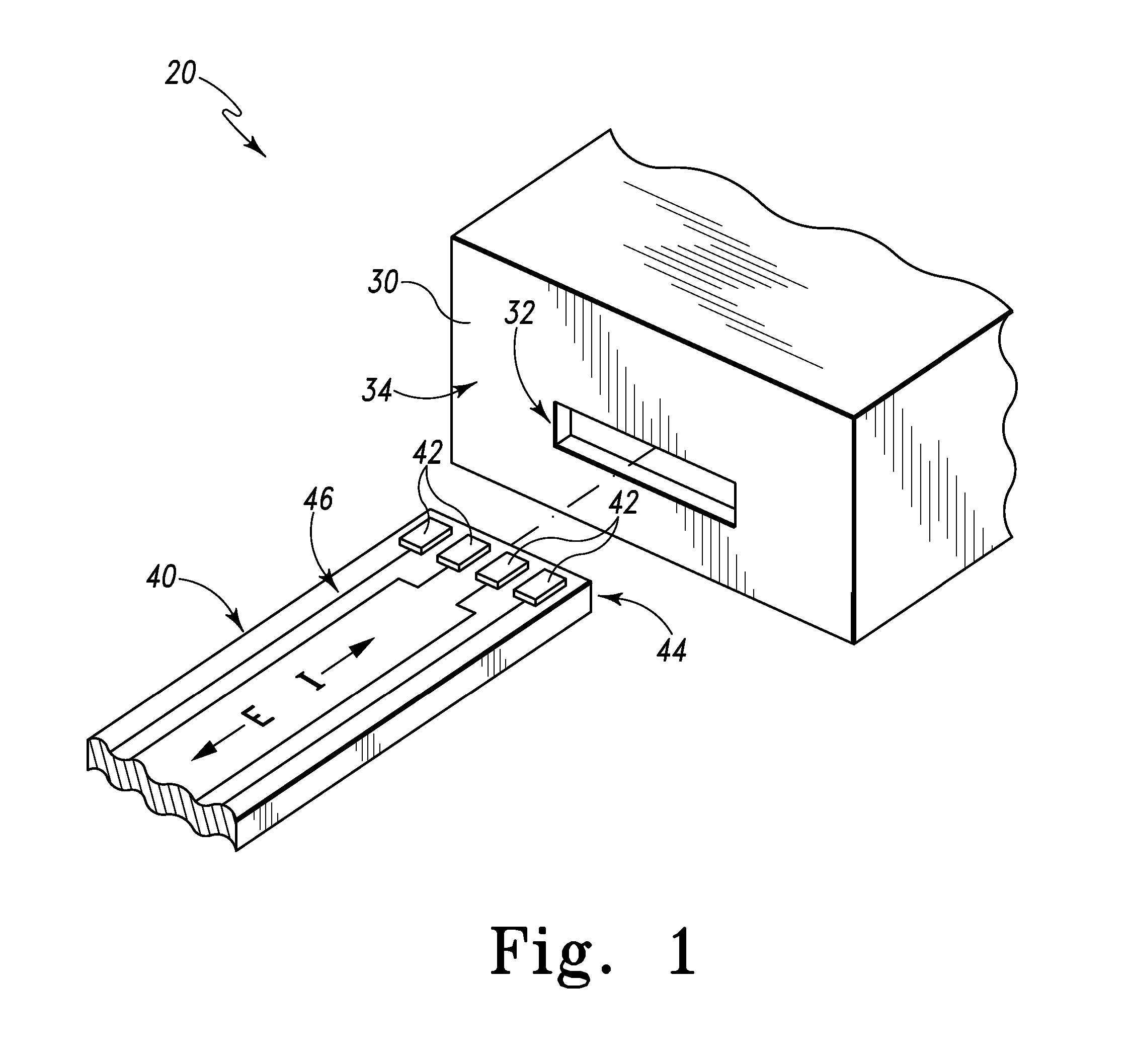
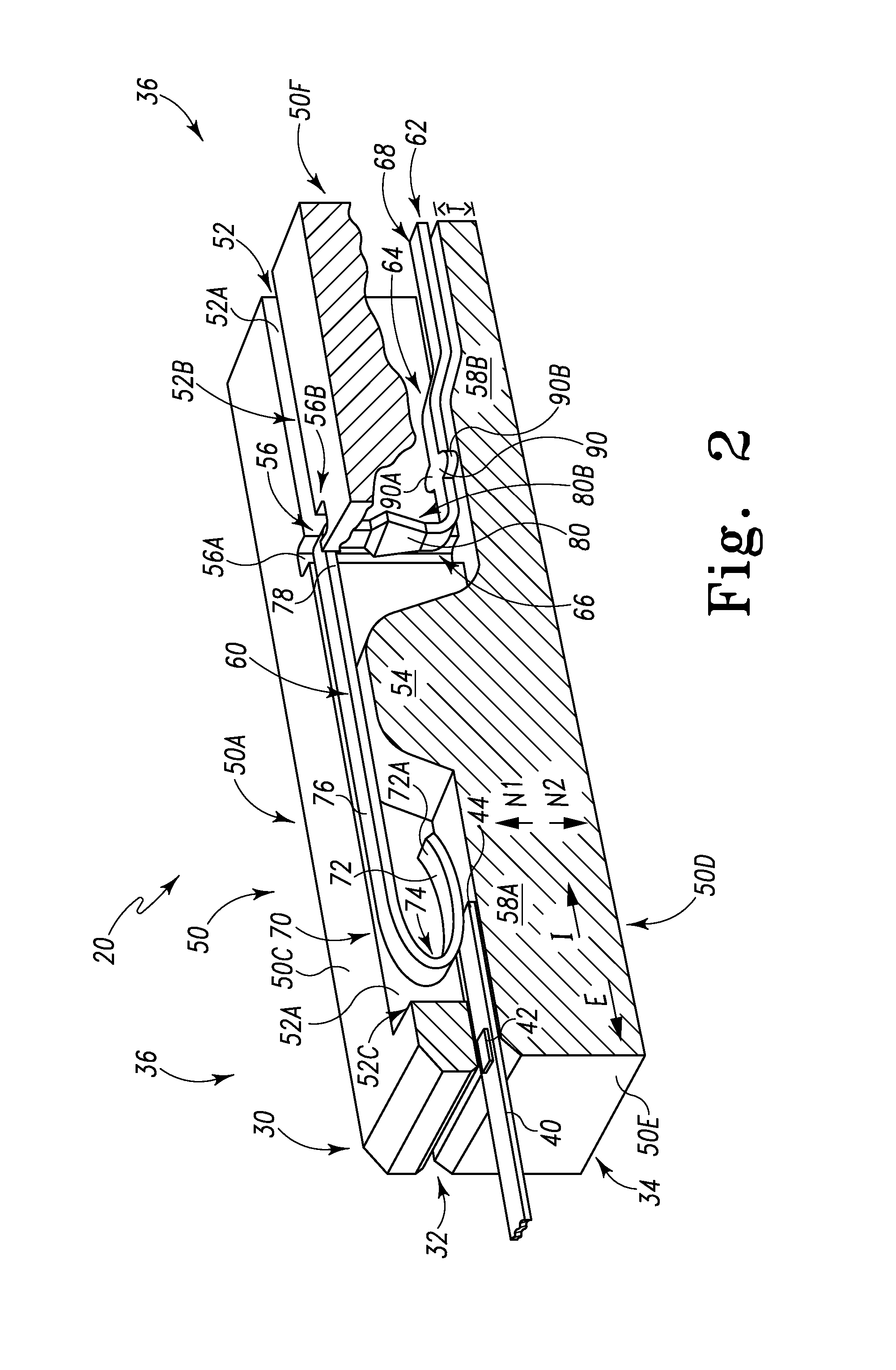
[0009]Some forms of the present invention improve user experience by increasing the probability of the test meter connector making a reliable contact with the inserted test strip. One form includes a system for measuring an analyte of interest in a biological fluid, where a connector provides an interface between a test strip bearing the biological fluid and a test meter. The analyte of interest is applied to a test strip having at least one contact pad for mating with the connector when the test strip is inserted through an opening in the meter housing. The connector comprises at least one contact wire disposed within the housing, where each contact wire has a distal portion and a proximal portion. The contact wire's proximal portion engages the connector housing and anchors the distal portion to the connector housing. The contact wire contacts the test strip upon insertion.
[0012]Yet another embodiment of the present invention is a device for testing an analyte on a test strip, comprising a connector having a plurality of contact wires. The proximal portion of each contact wire is fixed at least at one point within a connector housing. Part of the distal portion of each contact wire has a concave shape. In other embodiments, the contact wire has a convex-shaped portion. The “contact portion” of the contact wire that engages the test strip or contact pad has a desired radius of curvature, which may be at least about 3 mm, 4 mm, or 6 mm. Controlling the contact portion's radius of curvature reduces the frictional force that develops between the contact wire and test strip during insertion and removal, and minimizes the resulting abrasion.
[0014]Some embodiments further include rounding or smoothing the radius of curvature of the contact wire perpendicular to the direction of test strip insertion. Other embodiments of the present invention include a technique of plating the contact portion of the contact wire with soft, electrically conductive materials that are sacrificed during the test strip insertion and extraction process to minimize abrasion of the contact pad and other parts of the test strip. In certain other embodiments, the contact portion is plated with a non-gold material. Some embodiments include contact wires plated with soft metallic materials, and the wires each have a contact portion with a relatively small radius of curvature. In at least one such embodiment, a contact portion plated with a soft sacrificial material has a minimum radius of curvature less than 1 mm. Still other embodiments include techniques and features to minimize the normal force applied to the test strip by the distal portion during test strip insertion and extraction.
[0015]Other embodiments of the present invention include a minimally abrading connector comprising a single-piece connector housing and n contact wires held in a substantially rigid relationship. When the test strip is inserted into the connector, the n contact wires establish electrical contacts with the test strip's contact pads. Some embodiments have a further feature of staggering the position of the n contact wires in two, three, or more rows to increase the density of contact pad placement on test strips.

Problems solved by technology

Such thin film coatings are highly prone to scratching by current commercially available connectors.
Repeat insertions of the test strip (two to four times) can render these thin film-coated biosensors useless.
Even the first-time insertion of the test strip into the test meter may cause some removal of these thin film coatings by the test meter connector.
The result is a less reliable connection between the contact pad on a test strip and the connector contact wire in the test meter.
Abrasive contact between the connector contact wire and contact pad can reduce the longevity of the test meter connector, thereby further reducing the reliability of the system.

Method used


Image

  • Biological testing system and connector therefor
  • Biological testing system and connector therefor
  • Biological testing system and connector therefor

Examples


Embodiment Construction

[0031]For the purpose of promoting an understanding of the principles of the present invention, reference will now be made to the embodiment illustrated in the drawings and specific language will be used to describe the same. It will, nevertheless, be understood that no limitation of the scope of the invention is thereby intended; any alterations and further modifications of the described or illustrated embodiments, and any further applications of the principles of the invention as illustrated therein are contemplated as would normally occur to one skilled in the art to which the invention relates.

[0032]A system for testing blood according to the present invention enables greater contact density with higher reliability on thin film metallized plastic substrates. These higher densities enable one to include additional electrodes that are used in some embodiments to assure the measurement accuracy and reliability for supporting a fast, small volume test. Smaller samples, in turn, make...


PUM


Abstract

A connector for establishing electrical connection between a testing device and a test strip with a biological fluid thereon includes a contact pad on the test strip, and one or more contact wires in the testing device. When the strip is inserted into the testing device, part of the strip's end engages a contact portion of a contact wire and deflects it in a direction normal to the direction of insertion. In certain embodiments the radius of curvature (in the direction of insertion) of the contact portion is controlled to reduce abrasion of the strip by the wire. In other embodiments the radius of curvature (perpendicular to the direction of insertion) is controlled to reduce the abrasion of the strip by the wire. Sometimes the contact portion and / or contact pad is plated with a sacrificial material to reduce the coefficient of friction. In other embodiments various numbers of contacts receive the end of the strip substantially simultaneously, or are staggered in rows to distribute the resistance presented.

Description

PRIORITY CLAIM[0001]This patent application is a continuation of U.S. Ser. No. 11 / 409,383, filed on Apr. 21, 2006, now abandoned which is incorporated herein by reference in its entirety.TECHNICAL FIELD OF THE INVENTION[0002]The present invention relates to testing apparatus for testing the presence or concentration of one or more substances in a biological fluid, and more particularly to such a device that includes one or more electrical connections between a test strip (bearing a sample of the biological fluid) and a test meter.BACKGROUND OF THE INVENTION[0003]Measuring the concentration of substances, particularly in the presence of other substances, is important in many fields. This is especially true in medical testing and diagnosis. For example, the measurement of glucose in body fluids, such as blood, is crucial to the effective treatment of diabetes.[0004]Multiple methods are known for measuring the concentration of analytes, for example glucose, in a blood sample. Such meth...

Claims


Application Information

Patent Timeline
Patent Type & Authority Patents(United States)
IPC IPC(8): H01R4/48
CPCG01N27/3273
Inventor GROLL, HENNINGCELENTANO, MICHAEL J.FINNERTY, JOSEPH A.
Owner ROCHE DIABETES CARE INC
Learn More