Extreme ultraviolet light source apparatus

a light source and ultraviolet technology, applied in the field of extreme ultraviolet light source apparatus, can solve the problems of reducing reflectivity, affecting the effect affecting the emitted influence of ion particles and neutral particles, so as to achieve suppressed production of ion debris

Active Publication Date: 2013-03-19
GIGAPHOTON
View PDF8 Cites 8 Cited by
  • Summary
  • Abstract
  • Description
  • Claims
  • Application Information

AI Technical Summary

Benefits of technology

[0011]The present invention has been achieved in view of the above-mentioned problems. A purpose of the present invention is to provide an EUV light source apparatus in which contamination or damage of optical elements and other component elements by debris can be suppressed to realize longer lives of them.
[0013]According to the one aspect of the present invention, a magnetic field is generated by the magnetic field generating unit so as to control the state of at least one of the pre-plasma and the main plasma. As a result, production of ion debris can be suppressed and the produced ion debris can be removed by the magnetic field. Therefore, an EUV light source apparatus can be provided in which contamination and damage of optical elements and other component elements by debris can be suppressed to realize long life operation.

Problems solved by technology

In the LPP type EUV light source apparatus, there is a problem of an influence of ion particles and neutral particles emitted from the plasma.
If the ion debris collide with the target nozzle, the nozzle is sputtered and changed in the shape of tip of the nozzle, and thereby, positional stability of droplets may be deteriorated and materials sputtered from the nozzle may adhere to the collector mirror and so on and reduce the reflectivity.
Further, debris such as neutral particles cannot be trapped by the magnetic field but adhere to the surfaces of the collector mirror, and then, it causes the reflectivity reduction.

Method used


Image

  • Extreme ultraviolet light source apparatus
  • Extreme ultraviolet light source apparatus
  • Extreme ultraviolet light source apparatus

Examples


first embodiment

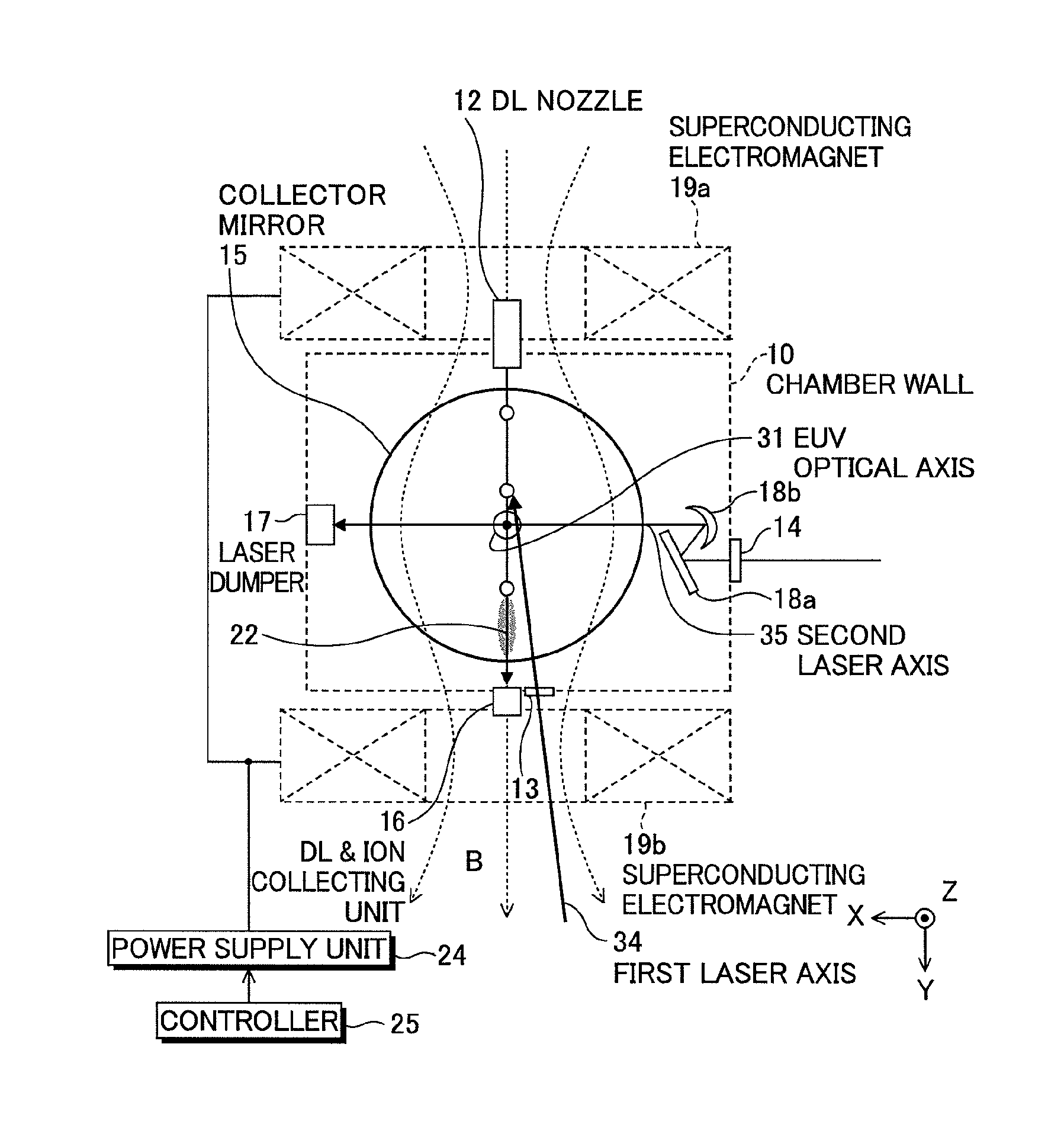
[0035]FIGS. 1A and 1B are a side view and a front view showing a schematic configuration of an extreme ultraviolet (EUV) light source apparatus according to the The extreme ultraviolet light source apparatus according to the embodiment employs a laser produced plasma (LPP) type for radiating EUV light by applying a laser beam to a target material for excitation. As shown in FIGS. 1A and 1B, the EUV light source apparatus includes a chamber defined by a chamber wall 10, a droplet (DL) nozzle 12, a first introduction window 13, a second introduction window 14, a collector mirror 15, a droplet and ion collecting unit 16, a laser dumper 17, superconducting electromagnets 19a and 19b, a power supply unit 24, a controller 25, and first and second laser oscillators (laser units) 50 and 60 (see FIG. 2B).

[0036]The droplet nozzle 12 injects a target material such as melted tin (Sn) supplied from a target supply unit through a bore of the superconducting electromagnet 19a, and thereby, suppli...

second embodiment

[0067]Next, the second embodiment will be explained.

[0068]FIGS. 6A and 6B are a side view and a partially enlarged perspective view showing an arrangement of five axes in an EUV light source apparatus according to the second embodiment.

[0069]While the superconducting electromagnets 19a and 19b are provided outside of the chamber in the first embodiment, the second embodiment is different in that small electromagnet coils (local magnetic field generating means) 19c and 19d are provided within the chamber. In the second embodiment, by employing the electromagnet coils 19c and 19d, a local magnetic field “B” is generated within the chamber. Due to the local magnetic field “B”, the pre-plasma is converged in the direction of the magnetic field “B”, flows after passing through the electromagnet coil 19d, and is collected in the collecting unit 16. It is desirable that the shadow on the EUV light path by the electromagnet coils 19c and 19d is minimized to arrange the electromagnet coils 1...

third embodiment

[0071]Next, the third embodiment will be explained.

[0072]FIGS. 7A and 7B are a side view and a partially enlarged perspective view showing an arrangement of five axes in an EUV light source apparatus according to the third embodiment.

[0073]While the first laser axis 34 passes inside of either one of the electromagnet coils 19c and 19d toward the droplet in the second embodiment, the first laser axis 34 passes outside of the electromagnet coils 19c and 19d, i.e., between the electromagnet coil 19c and the electromagnet coil 19d toward the droplet in the third embodiment.

[0074]According to the third embodiment, the laser oscillator for generating the first laser beam or the focusing optics for focusing the first laser beam can be provided out of alignment with the convergence direction of the pre-plasma and the main plasma for radiating the EUV light by the magnetic field, and thereby, the damage and contamination on the optics for the first laser beam by the ion debris generated from...


PUM


Abstract

An EUV light source apparatus in which contamination or damage of optical elements and other component elements by debris can be suppressed to realize longer lives of them. The EUV light source apparatus is an apparatus for radiating extreme ultraviolet light by generating plasma of a target material within a chamber, and includes: a first laser unit for applying a first laser beam to the target material to generate pre-plasma; a second laser unit for applying a second laser beam to the pre-plasma to generate a main plasma for radiating the extreme ultraviolet light; and a magnetic field generating unit for generating a magnetic field within the chamber to control a state of at least one of the pre-plasma and the main plasma.

Description

CROSS-REFERENCE TO RELATED APPLICATION[0001]The present application claims priority from Japanese Patent Applications No. 2008-250311 filed on Sep. 29, 2008 and No. 2009-125155 filed on May 25, 2009, the contents of which are incorporated herein by reference in their entirety.BACKGROUND OF THE INVENTION[0002]1. Field of the Invention[0003]The present invention relates to an extreme ultraviolet (EUV) light source apparatus to used as a light source in exposure equipment.[0004]2. Description of a Related Art[0005]In recent years, as semiconductor processes become finer, photolithography has been making rapid progress toward finer fabrication. In the next generation, microfabrication at 70 nm to 45 nm, further, microfabrication at 32 nm and beyond will be required. Accordingly, in order to fulfill the requirement for microfabrication at 32 nm and beyond, for example, exposure equipment is expected to be developed by combining an EUV light source for radiating EUV light having a wavelen...

Claims


Application Information

Patent Timeline
Patent Type & Authority Patents(United States)
IPC IPC(8): G01J3/10
CPCH05G2/001H05G2/008H05G2/003
Inventor ENDO, AKIRANAGAI, SHINJIKAKIZAKI, KOUJIWAKABAYASHI, OSAMUUENO, YOSHIFUMI
Owner GIGAPHOTON
Why Eureka
Try Eureka