Optical element driving apparatus, projection optical system, exposure apparatus and device manufacturing method

a driving apparatus and optical element technology, applied in the direction of cameras, printers, instruments, etc., can solve the problems of excessive driving load (weight) on the position adjustment mechanism, difficult to adjust the position and tilt of the optical elements with high accuracy, and further difficulty in the adjustment of the position and tilt so as to improve the positioning accuracy of the optical elements, the effect of suppressing the propagation of vibrations

Active Publication Date: 2013-03-19
NIKON CORP
View PDF20 Cites 12 Cited by
  • Summary
  • Abstract
  • Description
  • Claims
  • Application Information

AI Technical Summary

Benefits of technology

[0009](ii) Especially in a state in which the damper mechanism is arranged extending across the intermediate block and the fixed block, when the position adjustment mechanism moves the intermediate block and the additional mass, relative movement occurs between the magnets fixed to the intermediate block and the conductor plate supported on the fixed block. In this case, in the conductor plate, a damping force acting in an direction opposite the direction of the relative movement is generated by the conductor plate. The damping force affects the inherent driving force of the position adjustment mechanism, which is driven to adjust the position and tilt of the optical elements, and makes the adjustment of the position and tilt of the optical elements further difficult.
[0010]It is an object of the present invention to provide an optical element driving apparatus capable of adjusting at least either one of the position and tilt of optical elements in a satisfactory manner and improving the positioning accuracy of the optical elements while effectively suppressing the propagation of vibrations to the optical elements, to provide a projection optical system including the optical element driving apparatus, to provide an exposure apparatus including the projection optical system, and to provide a method for manufacturing a device with the exposure apparatus.
[0011]To achieve the above object, one aspect of the present invention provides an optical element driving apparatus including a fixed portion. A drive mechanism moves an optical element to adjust at least either one of the position and the tilt of the optical element relative to the fixed portion. A damper mechanism is arranged on the fixed portion to suppress propagation of vibrations to at least one of the optical element and the drive mechanism.

Problems solved by technology

Therefore, when the position adjustment mechanism adjusts the position and tilt of the optical elements, the exposure apparatus of Patent Document 1 causes the problems described below.
This causes the driving load (weight) on the position adjustment mechanism to become excessively high and makes it difficult to adjust the position and tilt of the optical elements with high accuracy.
The damping force affects the inherent driving force of the position adjustment mechanism, which is driven to adjust the position and tilt of the optical elements, and makes the adjustment of the position and tilt of the optical elements further difficult.

Method used


Image

  • Optical element driving apparatus, projection optical system, exposure apparatus and device manufacturing method
  • Optical element driving apparatus, projection optical system, exposure apparatus and device manufacturing method
  • Optical element driving apparatus, projection optical system, exposure apparatus and device manufacturing method

Examples


first embodiment

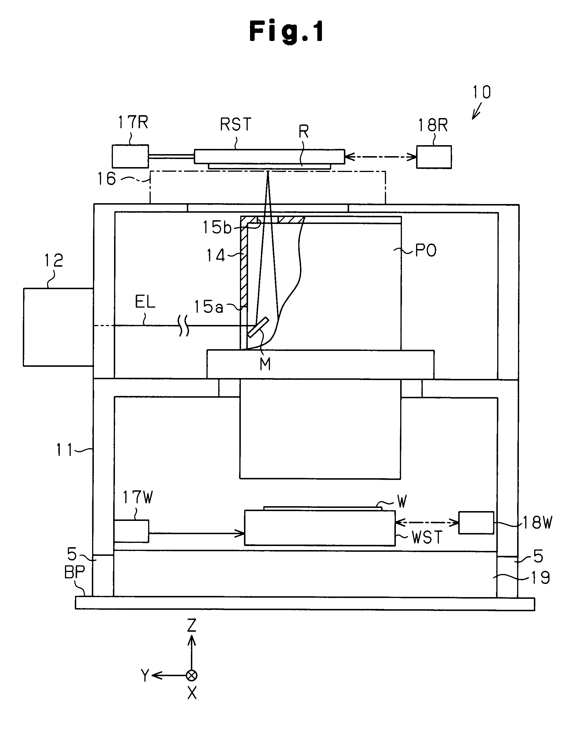
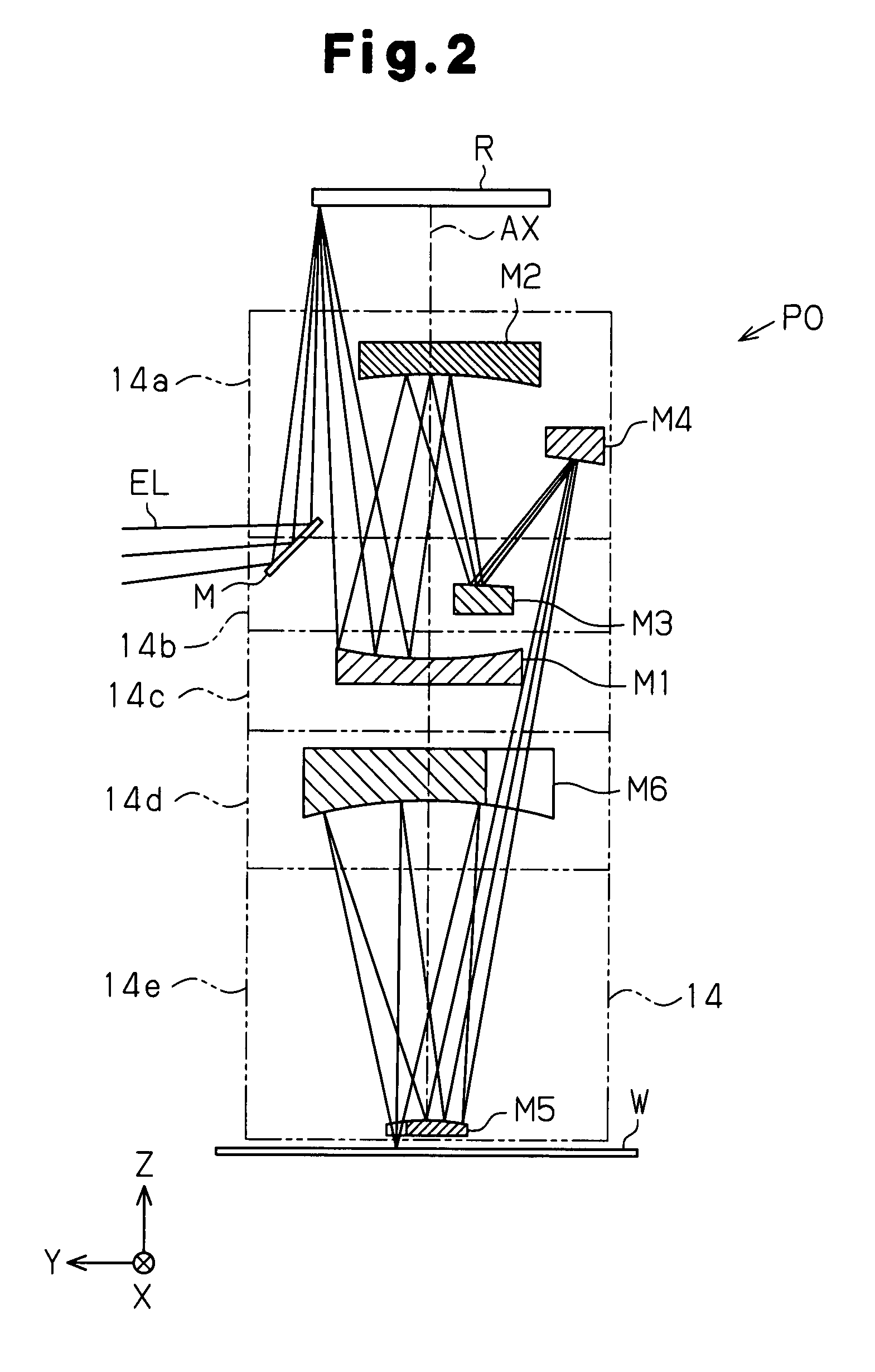
[0034]Referring to FIGS. 1 to 5, a scanning exposure apparatus according to the present invention will now be described. The scanning exposure apparatus is of a step-and-scan type and used to manufacture semiconductor devices.

[0035]As shown in FIG. 1, an exposure apparatus 10 is arranged in an evacuatable vacuum chamber (not shown) and includes a column frame 11 assembled above a base plate BP. A light source 12 is arranged on one side (left side as viewed in FIG. 1) of the column frame 11. A projection optical system PO is arranged in a generally central part of the column frame 11. An illumination optical system, which is not shown, is arranged between the projection optical system PO and the light source 12.

[0036]A vibration isolator 5 is arranged between the base plate BP and the column frame 11. This reduces disturbance vibrations transmitted to the base plate BP from the floor on which the exposure apparatus 10 is placed. The light source 12 may be arranged independently from ...

second embodiment

[0068]the present invention will now be described.

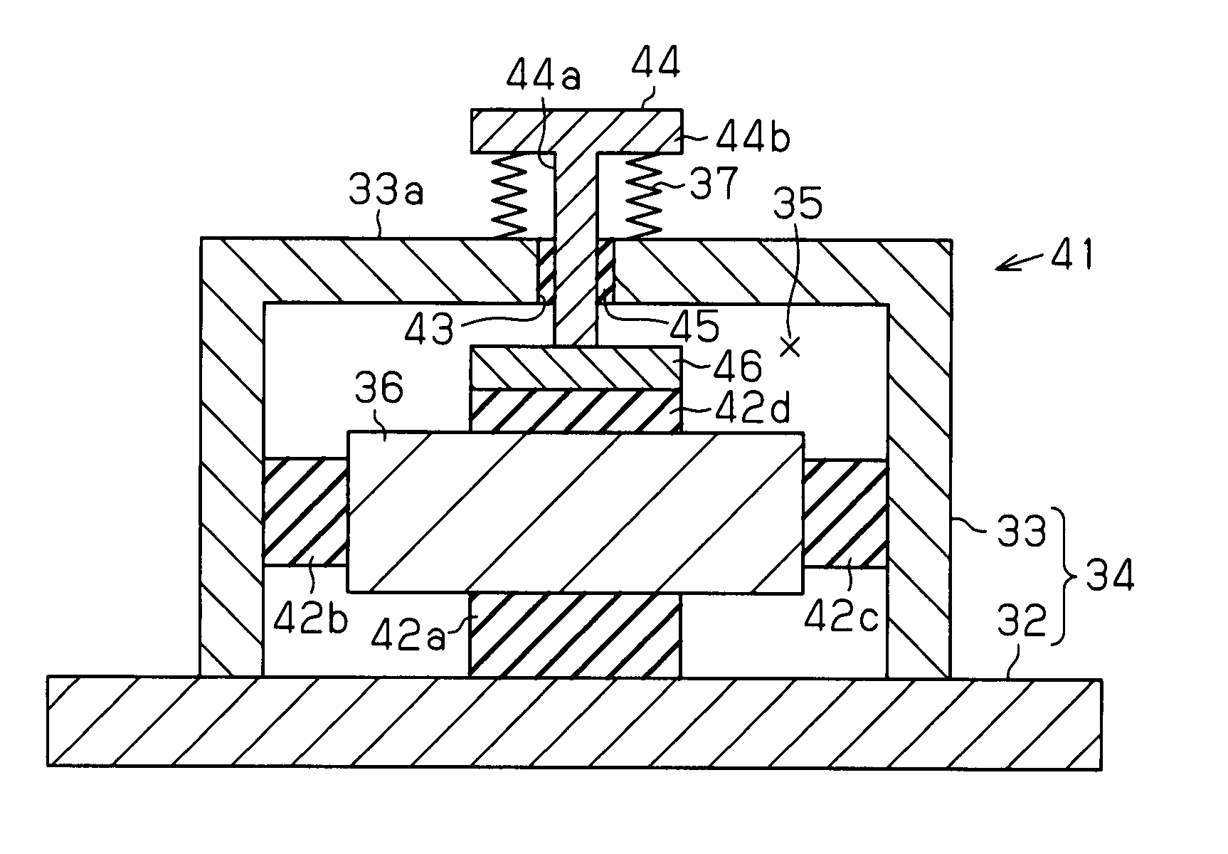
[0069]The second embodiment differs from the first embodiment only in the specific structure of the damper mechanism. The following description will be focused on the damper mechanism, and components that are the same as those of the first embodiment will be denoted by the same reference numerals and will not be described.

[0070]As shown in FIG. 6, in a damper mechanism 41 of the second embodiment, a casing 34, which includes a rectangular base member 32 fixed on an outer ring 21 and a cover 33 fixed on the base member 32, defines an hermetic chamber 35 having an atmospheric-pressure atmosphere. For example, an hermetic seal member may be arranged between the base member 32 and the cover 33 to improve the hermetic seal. A mass body 36 having a predetermined mass is arranged in the hermetic chamber 35. A rubber body 42a is arranged between the mass body 36 and the base member 32 to suppress displacement of the mass body 36 in the verti...


PUM


Abstract

An outer ring (21) is arranged in a barrel unit (14c). A driving mechanism (25) provided on the outer ring shifts an optical element (M), and adjusts the position and the tilt of the optical element. A damper mechanism (31) for suppressing propagation of vibration to the optical element is attached to the outer ring.

Description

TECHNICAL FIELD[0001]The present invention relates to an optical element driving apparatus for driving an optical element in an exposure apparatus that is used during a lithography process in a manufacturing process for a device, such as a semiconductor device and a liquid crystal display device, and a manufacturing process for a mask, such as a reticle and a photomask. The present invention also relates to a projection optical system and exposure apparatus including an optical element driving apparatus and a method for manufacturing a device with an exposure apparatus.BACKGROUND ART[0002]Generally, in a lithography process for manufacturing devices, such as a semiconductor device or a liquid crystal display device, an exposure apparatus is used to transfer a predetermined pattern formed in a mask, such as a reticle or a photomask, onto a substrate, such as a wafer or a glass plate, to which resist is applied, via projection optical system. The transferred pattern is miniaturized to...

Claims


Application Information

Patent Timeline
Patent Type & Authority Patents(United States)
IPC IPC(8): G03B27/42G02B7/02
CPCG02B7/1827G03F7/70266G03F7/70825G03F7/709G02B7/005G02B17/06G03F7/70808
Inventor ISHIKAWA, MITSUO
Owner NIKON CORP
Why Eureka
Try Eureka