Proximity sensor, in particular microphone for reception of sound signals in the human audible sound range, with ultrasonic proximity estimation

a proximity sensor and microphone technology, applied in the field of proximity sensors, can solve the problems of lowering the sales margin of such devices, neither the proximity sensor nor the gravitational force sensor is capable of detection, etc., and achieves the effects of reducing hardware complexity, reducing the resonance frequency, and reducing the installation space and manufacturing steps

Active Publication Date: 2013-03-19
NXP BV
View PDF15 Cites 20 Cited by
  • Summary
  • Abstract
  • Description
  • Claims
  • Application Information

AI Technical Summary

Benefits of technology

[0023]An embodiment of the invention can provide an arrangement which enables sound input and omits expensive additional actuator / sensor arrangements for estimating the proximity of a device to the user.
[0027]Another example is the integration of such microphones in the dashboard of a car. The position of a driver and / or co-driver can be detected and the microphone array can be used to implement angular sensitive voice recording. This is an advantage to reduce background noise. The ultrasonic detection of the body of the driver enables a more focused beam steering than when using conventional microphones.
[0031]From U.S. Pat. No. 5,870,482 and US 2005 / 0018864 it is known that miniature silicon condenser microphones have many advantages over normal sized microphones, as they can be integrated with CMOS circuitry, do not need an electret. An electret is a stable dielectric material with a permanently-embedded static electric charge (which, due to the high resistance and chemical stability of the material, will not decay for hundreds of years). Since miniature silicon condenser microphones do not need an electret for electrical biasing they are easier to solder onto a printed circuit board (PCB) than the conventional electret microphones. Additionally, they have a form factor compatible with state-of-the-art hand-held device architectures and can be made by batch processing which makes the device to device variation much smaller.
[0037]The inventors have perceived that a large variety of electronic devices benefit from voice control or sound input capability on one hand and from proximity estimation and / or gesture control capability on the other hand. The groundbreaking idea is to lower hardware complexity, mounting space and manufacturing steps by using an acoustic transducer for voice and sound reception in the audible frequency range as well as for ultrasonic distance or proximity detection.
[0044]In another embodiment at least two acoustic transducers, as herein proposed, are provided in an electronic device. In the next years, the number of acoustic transducers employed per mobile device is expected to grow in order to enable acoustical directivity sensing, e.g. to locate a speaker or a sound source in a conferencing mode of the device. This enables angular detection of the presently speaking person by runtime delay between signals received at different distances from the speaking person and thus the device may acoustically focus towards this person like conference phones can do. Possible applications are computer monitors and dashboards of motor vehicles. Thus, the effect of ambient noise and / or motor sound on speech intelligibility of a phone call can significantly be reduced.
[0047]Accordingly, the component comprises at least one herein proposed proximity sensor (arrangement) and several terminals for electric power supply of the component, for triggering the proximity estimation and for signalling the proximity estimation result. The advantage of such a component is, that the component can easily be adapted for many different surrounding electronic circuits. Connection of the component to those electronic circuits is kept simple, because the features are realized as far as possible in the component. Thus adaptation expenses are reduced and only few terminals have to be connected. For example, two terminals may be adapted to provide power supply to the component, one terminal can be provided for triggering the component to execute the proximity estimation step and a last terminal can be provided for the signalling regarding the proximity estimation result of the component. Those skilled in the art of circuitry know how to further reduce the number of necessary terminals by alternately triggering the proximity estimation step and receiving the proximity estimation result over one and the same terminal.

Problems solved by technology

However, neither the proximity sensor nor the gravitational force sensor is capable to detect, whether the phone is held next to the ear during a call or in front of a face to watch the display.
Thus, expensive additional actuator / sensor arrangements for estimating the proximity of a device and voice / sound input capability significantly lower the sales margins of such devices.

Method used


Image

  • Proximity sensor, in particular microphone for reception of sound signals in the human audible sound range, with ultrasonic proximity estimation
  • Proximity sensor, in particular microphone for reception of sound signals in the human audible sound range, with ultrasonic proximity estimation
  • Proximity sensor, in particular microphone for reception of sound signals in the human audible sound range, with ultrasonic proximity estimation

Examples


Embodiment Construction

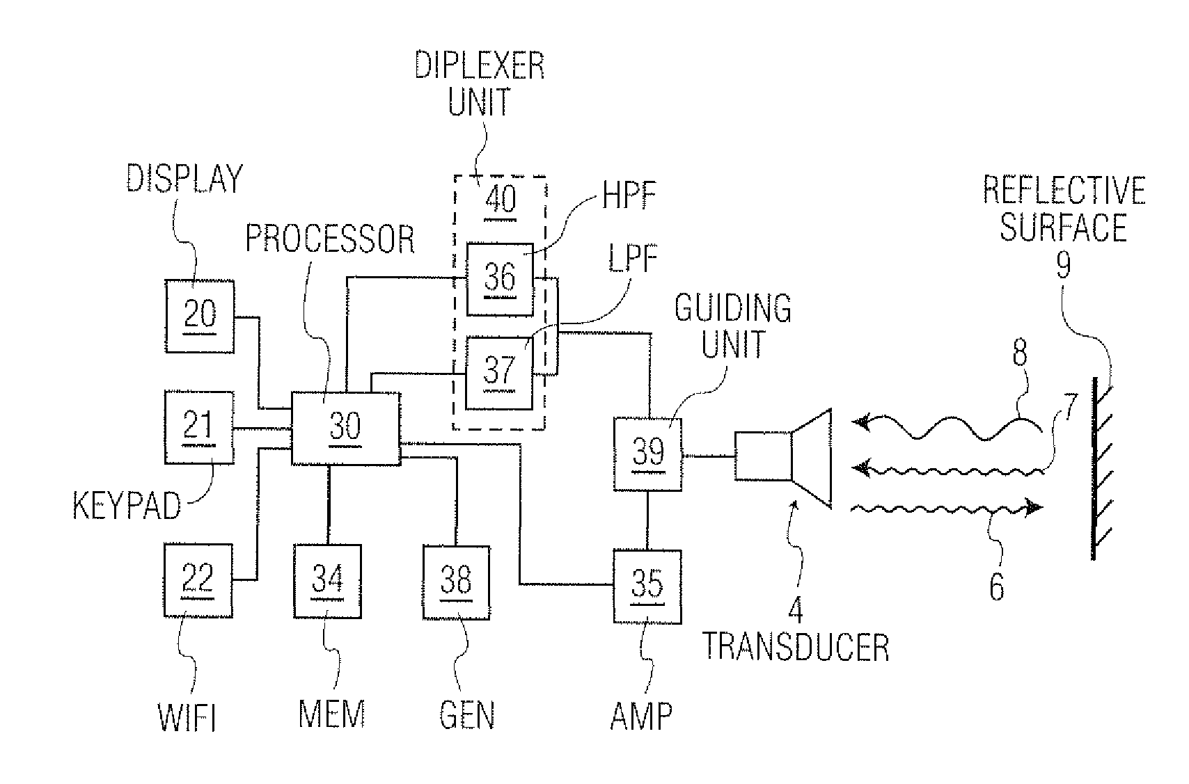
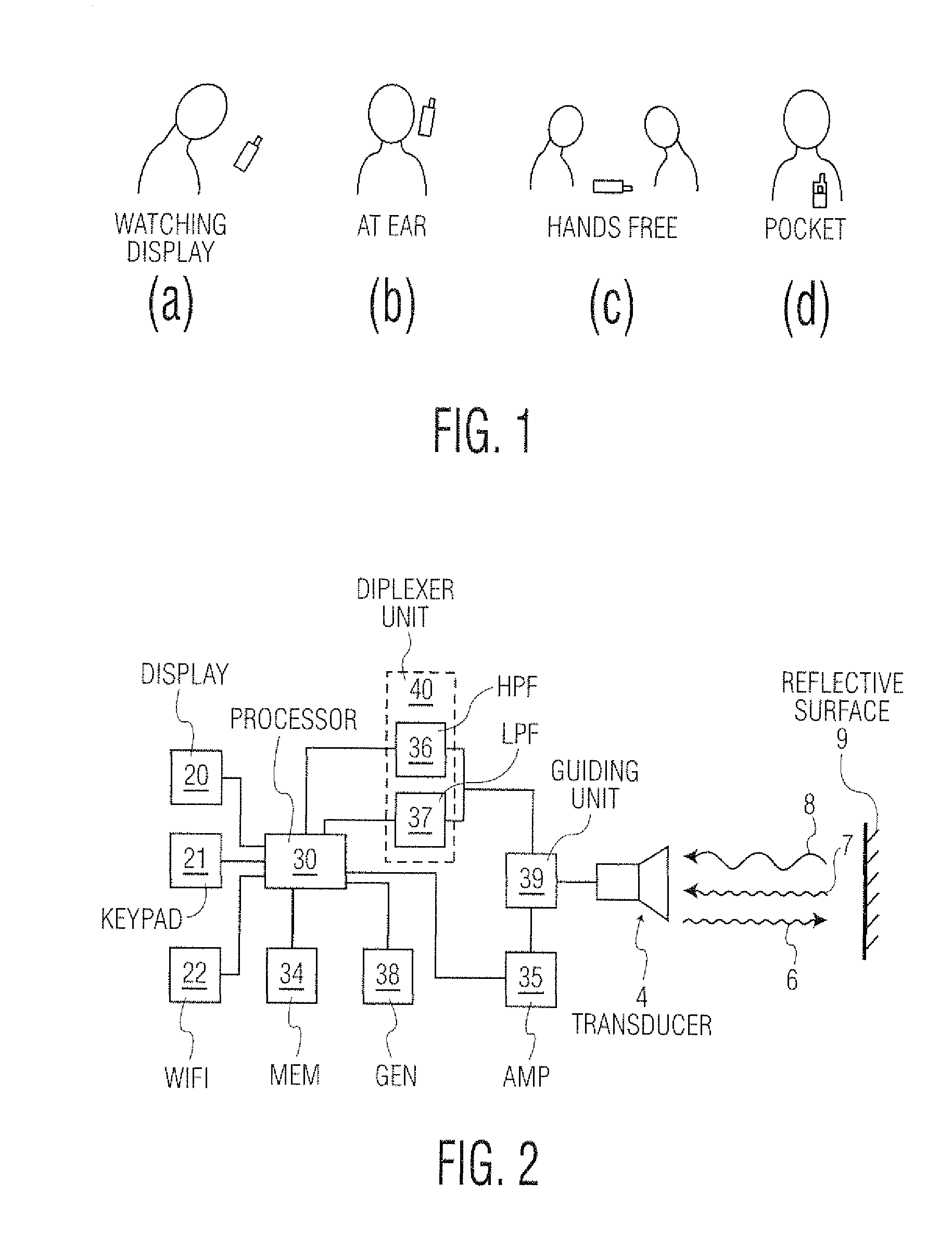
[0058]Now reference is made to FIG. 2, which shows a block diagram of the basic elements of a proximity sensor according to one aspect of the present solution. A signal generator 38 provides a signal in the ultrasonic sound range, preferably a burst, to processor 30. If processor 30 decides to initiate the proximity estimation step, it passes the received ultrasonic signal burst from signal generator 38 to power amplifier 35. Power amplifier 35 passes the ultrasonic signal burst to guiding unit 39, which guides the signal to the acoustic transducer 4. Guiding unit 39 may comprise a hybrid termination circuit or other appropriate means to alternating use acoustic transducer 4 as an emitter (actuator) in one moment and as a receiver (sensor) in another moment. Acoustic transducer 4 emits ultrasonic signal 6 and in case ultrasonic signal 6 impinges a reflective surface 9, reflected ultrasonic signal 7 again impinges on acoustic transducer 4.

[0059]Along with reflected ultrasonic signal ...


PUM


Abstract

Proximity sensor, particularly for usage in an electronic mobile device, comprising at least one acoustic transducer adapted for receiving acoustic signals at least in parts of the frequency range of human audible sound and emitting and / or receiving ultrasonic signals for proximity estimation. The acoustic transducer preferably is a Micro-Electro-Mechanical-Systems (MEMS) microphone. Further, a method in an electronic device comprising an acoustic transducer is provided comprising the steps of generating at least one electric signal in the frequency range of ultrasonic sound, emitting at least one ultrasonic signal by means of the acoustic transducer; receiving at least one ultrasonic signal by means of the acoustic transducer; deducing from the at least one emitted ultrasonic signal and the at least one received ultrasonic signal at least the delay between emission of the emitted ultrasonic signal and reception of the corresponding ultrasonic signal.

Description

[0001]This application claims the priority under 35 U.S.C. §119 of European patent application no. 09164437.7, filed on Jul. 2, 2009, the contents of which are incorporated by reference herein.FIELD OF THE INVENTION[0002]The present invention in general relates to an acoustic transducer for estimating the distance or position of an electronic device relative to the user. In particular, the present invention relates to usage of a Micro-Electro-Mechanical-Systems (MEMS) microphone for reception of sound signals in the human audible sound range on one hand and emitting and / or receiving ultrasonic signals for proximity estimation on the other hand.BACKGROUND OF THE INVENTION[0003]Electronic devices, especially handheld devices, are getting smarter and smarter. For instance, the equipment or device is able to anticipate activities of the user thus instead of the user having to operate the device in order to adjust its settings to a new situation and / or position, “intelligent” functions, ...

Claims


Application Information

Patent Timeline
Patent Type & Authority Patents(United States)
IPC IPC(8): H04M9/00
CPCG01S15/06H03K17/94H04R19/005H04R19/04G01S15/876H03K2217/94005H04R2400/01H04M1/6016H04M1/72454
Inventor LANGEREIS, GEERTVAN LIPPEN, TWANDIRKSEN, PETERPASVEER, FRANK
Owner NXP BV
Why Eureka
Try Eureka