
Modular tapered hollow reamer for medical applications

a tapered hollow reamer and modular technology, applied in the field of medical applications, can solve the problems of not being easily accessible with a straight shaft, and achieve the effects of reliably transferring shaft torque, reducing the possibility of bone fragment incorporation into living bone tissue, and preventing wobbliness of cutting

Active Publication Date: 2013-03-26
LRS SCI & TECH LLC
View PDF46 Cites 6 Cited by
  • Summary
  • Abstract
  • Description
  • Claims
  • Application Information

AI Technical Summary

Benefits of technology

The modular design allows for fresh cutter assemblies with each use, maintaining cutting efficiency and reducing the risk of bone necrosis and fat embolism by isolating bone debris, thus improving surgical safety and performance.

Problems solved by technology

A flexible shaft permits reaming of bone tissue that is not directly in line and therefore not easily accessible with a straight shaft.

Method used


Image

  • Modular tapered hollow reamer for medical applications
  • Modular tapered hollow reamer for medical applications
  • Modular tapered hollow reamer for medical applications

Examples


first embodiment

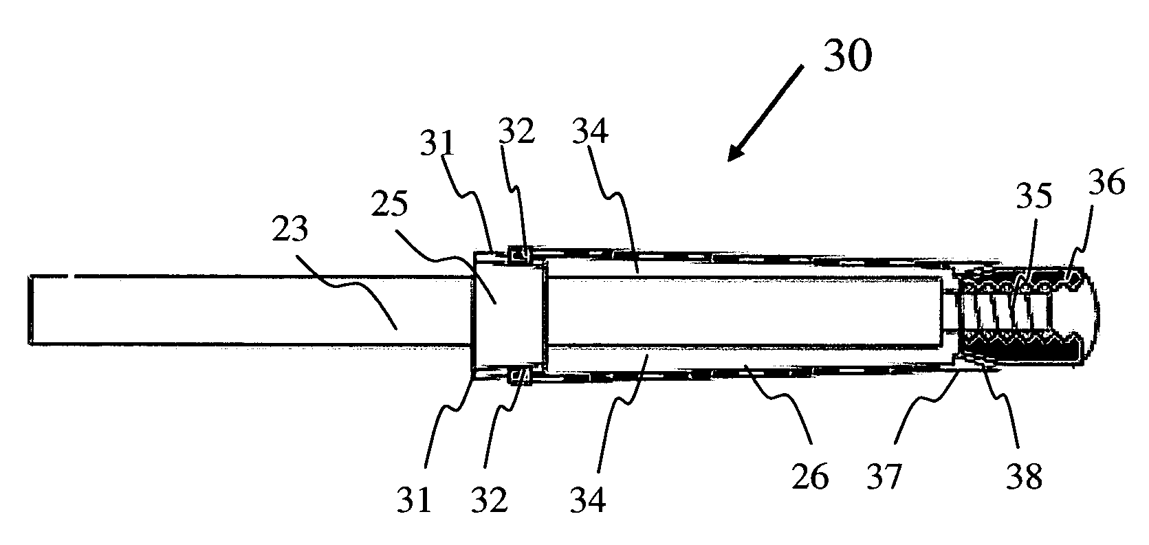
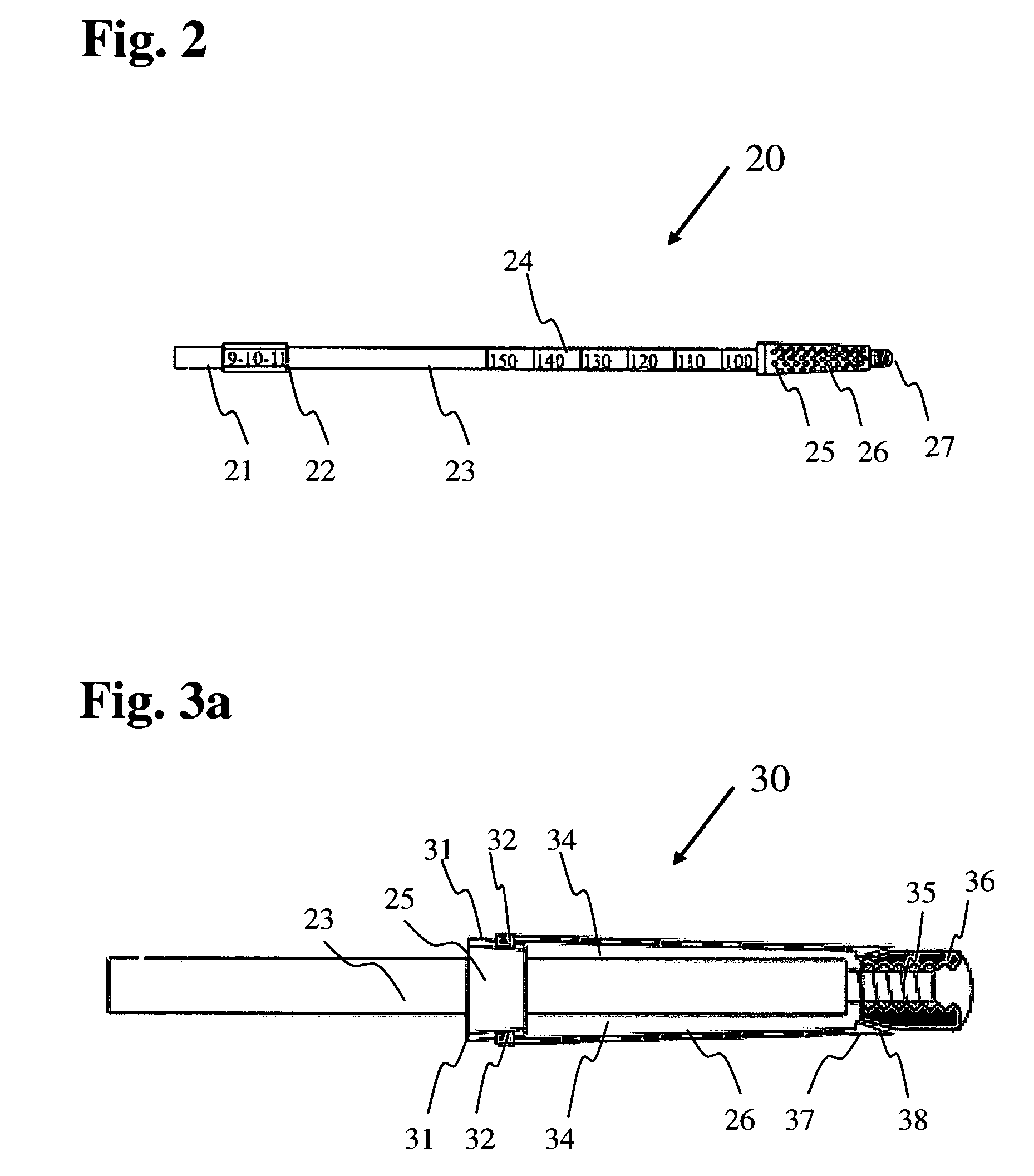
[0048]FIG. 3a depicts at 30 the mechanical attachment details of the modular disposable tapered hollow reamer assembly according to the Identical indicia are used to keep track of various components. The reusable shaft 23 has the shaft cone element 25 with one or more slots 31, one above and one below are shown. The tapered hollow reamer sleeve 26 has two torque transmitting tabs 32 engaging into the slots 31 of the shaft cone element 25. As a result, when the shaft 23 is rotated, the tapered hollow reamer sleeve is also rotated with no slippage. The distal end of the tapered hollow reamer is provided with a collet taper as shown at 37. The distal end of the shaft 23 is threaded as shown at 35. A modular pilot 27 has female threads 36 that mate with the shaft distal end threads. The modular pilot has a collet taper at 38 that mates with the collet taper 37 of the tapered hollow reamer, centering the reamer as it is tightened. The space 34 that is between tapered hollow reamer sleev...

second embodiment

[0049]FIG. 3b depicts at 30 the mechanical attachment details of the modular disposable tapered hollow reamer assembly according to the Identical indicia are used to keep track of various components. The reusable shaft 23 has the shaft cone element 25 with one or more slots 31 (one above and one below are shown). The tapered hollow reamer sleeve 26 has two torque transmitting tabs 32 engaging into the slots 31 of the shaft cone element 25. As a result, when the shaft 23 is rotated, the tapered hollow reamer sleeve is also rotated with no slippage. The distal end of the tapered hollow reamer is provided with a collet taper as shown at 37. The distal end of the shaft 23 has female threads as shown at 35. A modular pilot 27 has male threads 36 that mate with the shaft distal end threads. The modular pilot has a collet taper at 38 that mates with the collet taper 37 of the tapered hollow reamer, centering the reamer as it is tightened. The space 34 that is between tapered hollow reamer...


PUM


Abstract

An easy-to-assemble reamer for medical applications includes a shaft portion, a disposable tapered hollow reamer sleeve and a modular pilot. The shaft portion has a proximal end for attachment to a drill, a central cone element with one or more slots and a distal threaded end. The tapered hollow reamer sleeve has integrally attached one or more torque transmitting tabs at the larger end and a collet taper at the smaller end and slides over the shaft distal end engaging tabs with the slots. The modular pilot has a threaded central aperture engaging shaft thread and a collet taper mating with the collet taper of the reamer sleeve substantially coinciding their centerlines. The disposable hollow cutter sleeve has a plurality of cutting elements and apertures that discharge bone and bone cement debris into the space between the reamer and the shaft. With this construction, the reamer transmits reliable, wobble free, reaming torque in a highly efficient manner.

Description

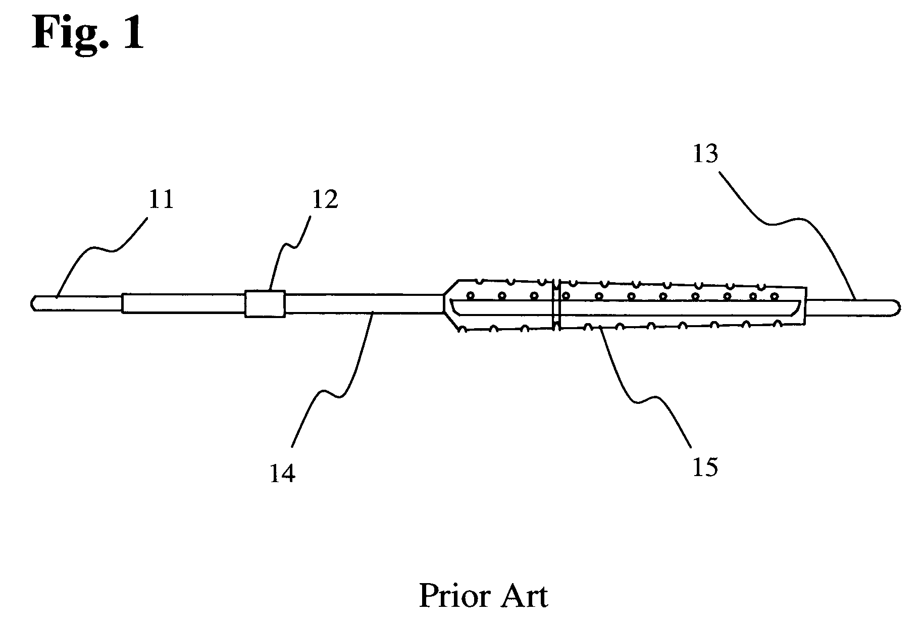
[0001]This is a Continuation-In-Part of application Ser. No. 11 / 704,754, Filed Feb. 9, 2007 for “Hollow Reamer For Medical Applications”, and application Ser. No. 11 / 973,260, Filed Oct. 5, 2007 for “Modular Tapered Hollow Reamer For Medical Applications”, the disclosures of which are hereby incorporated in their entirety by reference thereto.BACKGROUND OF THE INVENTION[0002]1. Field of the Invention[0003]The present invention relates to a modular easy-to-assemble tapered hollow reamer for medical applications; and more particularly, to a hollow tapered reamer having a disposable reamer assembly, which can be attached to a reusable shaft portion and includes a bone debris capturing cavity.[0004]2. Description of the Prior Art[0005]Reaming of the internal canal of bones is required in many surgical procedures of orthopedic surgery. These procedures include hip replacement, knee replacement and shoulder replacement. Reamers are also used in procedures that involve the internal fixation...

Claims


Application Information

Patent Timeline
Patent Type & Authority Patents(United States)
IPC IPC(8): A61B17/00
CPCA61B17/1617A61B17/1637A61B2017/0023A61B2017/00464A61B2019/446A61B90/94
Inventor SIDEBOTHAM, CHRISTOPHER G.LEWIS, RANDALL J.
Owner LRS SCI & TECH LLC
Learn More