Carbon nanotube film composite structure, transmission electron microscope grid using the same, and method for making the same

a carbon nanotube and composite structure technology, applied in nuclear engineering, electric/magnetic/electromagnetic heating, etc., can solve the problems of high background noise in transmission electron microscopy imaging, low loading efficiency of specimens of the tem grid disclosed by zhang et al., and difficult observation of the large amount of specimens distributed in a plan

Active Publication Date: 2013-03-26
TSINGHUA UNIV +1
View PDF13 Cites 5 Cited by
  • Summary
  • Abstract
  • Description
  • Claims
  • Application Information

AI Technical Summary

Benefits of technology

[0005]Transmission electron microscopy is one of the most important techniques available for the detailed examination and analysis of very small materials. Transmission electron microscopy provides high resolution imaging and material analysis of thin specimens. In transmission electron microscopy analysis, a transmission electron microscope (TEM) grid is used to support the sample such as specimens. The conventional TEM grid includes a metal grid such as a copper or nickel grid, a porous organic membrane covering on the metal grid, and an amorphous carbon film deposited on the porous organic membrane. However, in practical application, when the size of the specimen corresponds to or is less than the thickness of the supporting film, especially when the specimen is nano in size, the amorphous carbon film induces high background noise in the transmission electron microscopy imaging.

Problems solved by technology
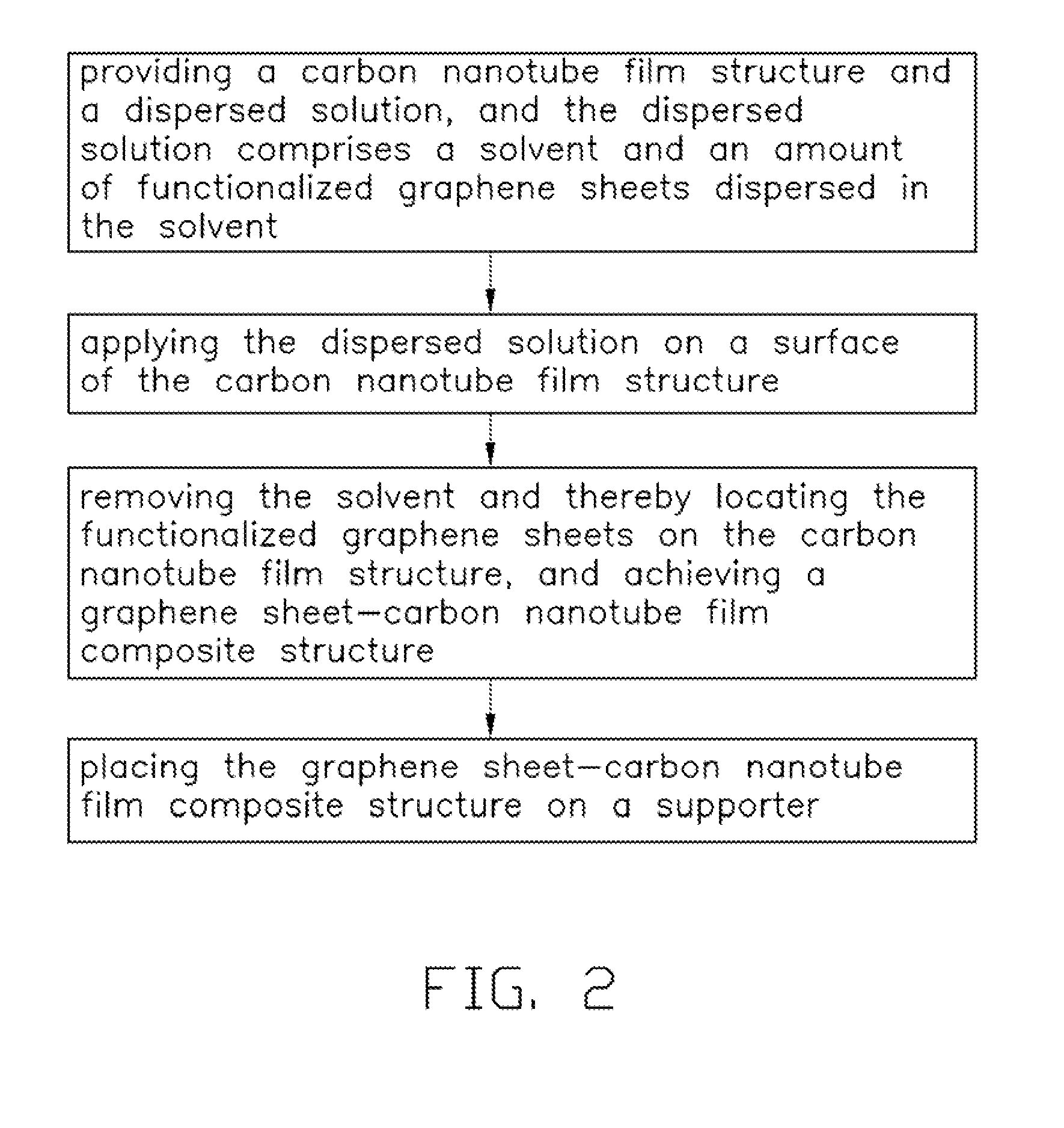
However, in practical application, when the size of the specimen corresponds to or is less than the thickness of the supporting film, especially when the specimen is nano in size, the amorphous carbon film induces high background noise in the transmission electron microscopy imaging.
However, the loading efficiency for the specimens of the TEM grid disclosed by Zhang et al. is relatively low.
Although observation of individual specimens can be done by using the TEM grid, it is not easy to observe the entire distribution of the large amount of specimens distributed in a plane.

Method used


Image

  • Carbon nanotube film composite structure, transmission electron microscope grid using the same, and method for making the same
  • Carbon nanotube film composite structure, transmission electron microscope grid using the same, and method for making the same
  • Carbon nanotube film composite structure, transmission electron microscope grid using the same, and method for making the same

Examples


Embodiment Construction

[0021]The disclosure is illustrated by way of example and not by way of limitation in the figures of the accompanying drawings in which like references indicate similar elements. It should be noted that references to “another”, “an”, or “one” embodiment in this disclosure are not necessarily to the same embodiment, and such references mean at least one.

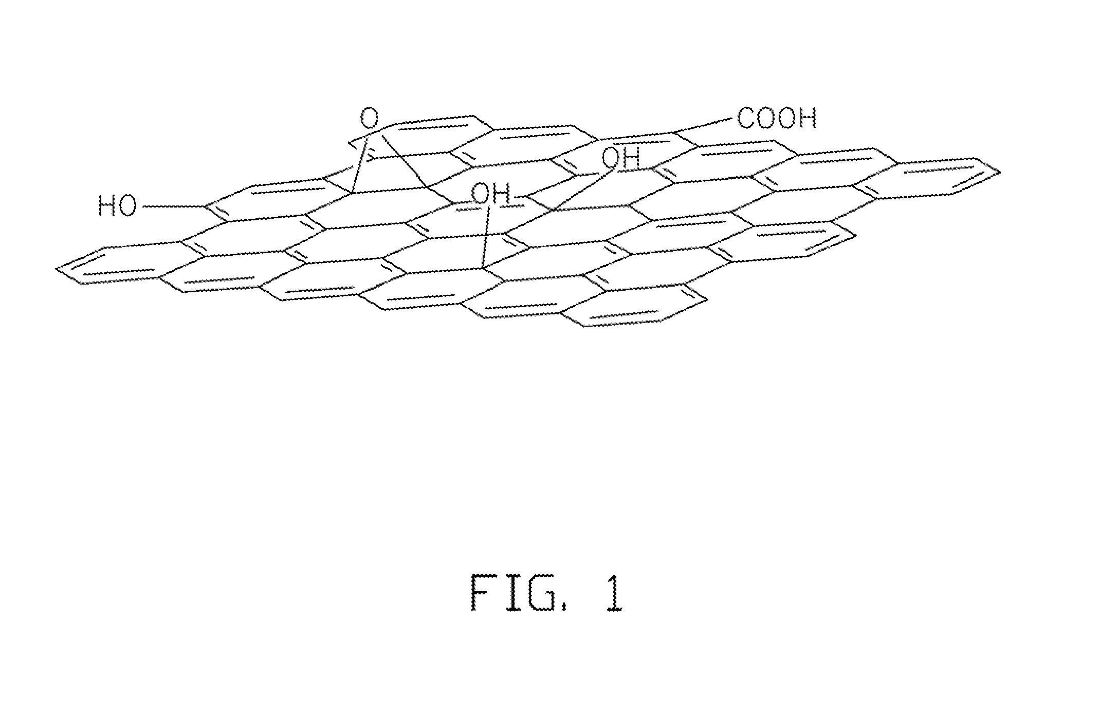
[0022]Graphite has a multi-layer structure in which two-dimensional atomically fundamental layers are laminated, whereas graphene has a single atomically fundamental layer. In the following description, a very thin graphite is referred to as a graphene sheet, and may include 1 to 10 laminated layers of graphene. The graphene can be covalently or non-covalently functionalized (such as due to electrovalent bonds, hydrogen bonds, and / or π-π bonds) to form a functionalized graphene. The functionalized graphene may include graphene as a basal-plane and one or more functional groups joined to carbon atoms of the graphene. The functionalized...


PUM

PropertyMeasurementUnit
diameteraaaaaaaaaa
heightaaaaaaaaaa
heightaaaaaaaaaa

Abstract

The present invention relates to a method for making a graphene sheet-carbon nanotube film composite structure. The method includes steps of: providing a carbon nanotube film structure and a dispersed solution, and the dispersed solution comprises a solvent and an amount of functionalized graphene sheets dispersed in the solvent; applying the dispersed solution on a surface of the carbon nanotube film structure; and removing the solvent and thereby locating the functionalized graphene sheets on the carbon nanotube film structure. The present invention also relates to a method for making a transmission electron microscope grid.

Description

CROSS-REFERENCE TO RELATED APPLICATIONS[0001]This application claims all benefits accruing under 35 U.S.C. §119 from China Patent Application No. 201010126408.5, filed on 2010 Mar. 17 in the China Intellectual Property Office, the disclosure of which is incorporated herein by reference. This application is related to commonly-assigned application entitled, “CARBON NANOTUBE FILM COMPOSITE STRUCTURE, TRANSMISSION ELECTRON MICROSCOPE GRID USING THE SAME, AND METHOD FOR MAKING THE SAME”, filed 2010 Oct. 19, Ser. No. 12 / 907,508.BACKGROUND[0002]1. Technical Field[0003]The present disclosure relates to a carbon nanotube film composite structure, a transmission electron microscope grid using the same, and a method for making the same.[0004]2. Description of Related Art[0005]Transmission electron microscopy is one of the most important techniques available for the detailed examination and analysis of very small materials. Transmission electron microscopy provides high resolution imaging and ...

Claims


Application Information

Patent Timeline
Patent Type & Authority Patents(United States)
IPC IPC(8): B29C65/00B32B38/04B32B37/00
CPCH01J37/20H01J37/26Y10T156/108Y10T156/1052
Inventor ZHANG, LI-NAJIANG, KAI-LIZHOU, RUI-FENGFAN, SHOU-SHAN
Owner TSINGHUA UNIV
Why Eureka
Try Eureka