

Methods and devices for ultra smooth substrate for use in thin film solar cell manufacturing
a technology of solar cells and substrates, applied in the field of substrates, can solve the problems of limited mechanical rolling in alloys or materials, poor quality, and limited material number, and achieve the effects of preventing smoothening, achieving desired smoothness, and reducing manufacturing costs
Inactive Publication Date: 2013-04-02
AERIS CAPITAL SUSTAINABLE IP
View PDF1 Cites 3 Cited by
- Summary
- Abstract
- Description
- Claims
- Application Information
AI Technical Summary
Benefits of technology
The patent text describes a method for smoothing the surface of a metal substrate using a plating additive or grain refiner to create a small grain structure that improves the filling of rough surfaces. This allows for smoother surfaces without creating a mirror of the original roughness. The method also involves flowing a second material into the depressed surface portions of the substrate to build up a new top surface having a roughness of about 0.05 microns or smoother. The resulting smooth surface is suitable for various applications such as vacuum deposition processes or high pressure rollers. The method allows for filling that does not delaminate and creates a multi-metal foil that has higher electrical conductivity than the original foil. The backside of the foil can remain rough or can be insulated to prevent electrical contact or chemical reactivity issues. The method creates a substrate with a surface layer of a second material creating a connective network or layer linking all valleys in the substrate together.
Problems solved by technology
One of the main cost drivers is making it smooth with mirror finish requires different, expensive rolling process that also limits the number of materials which can be processed to such finish.
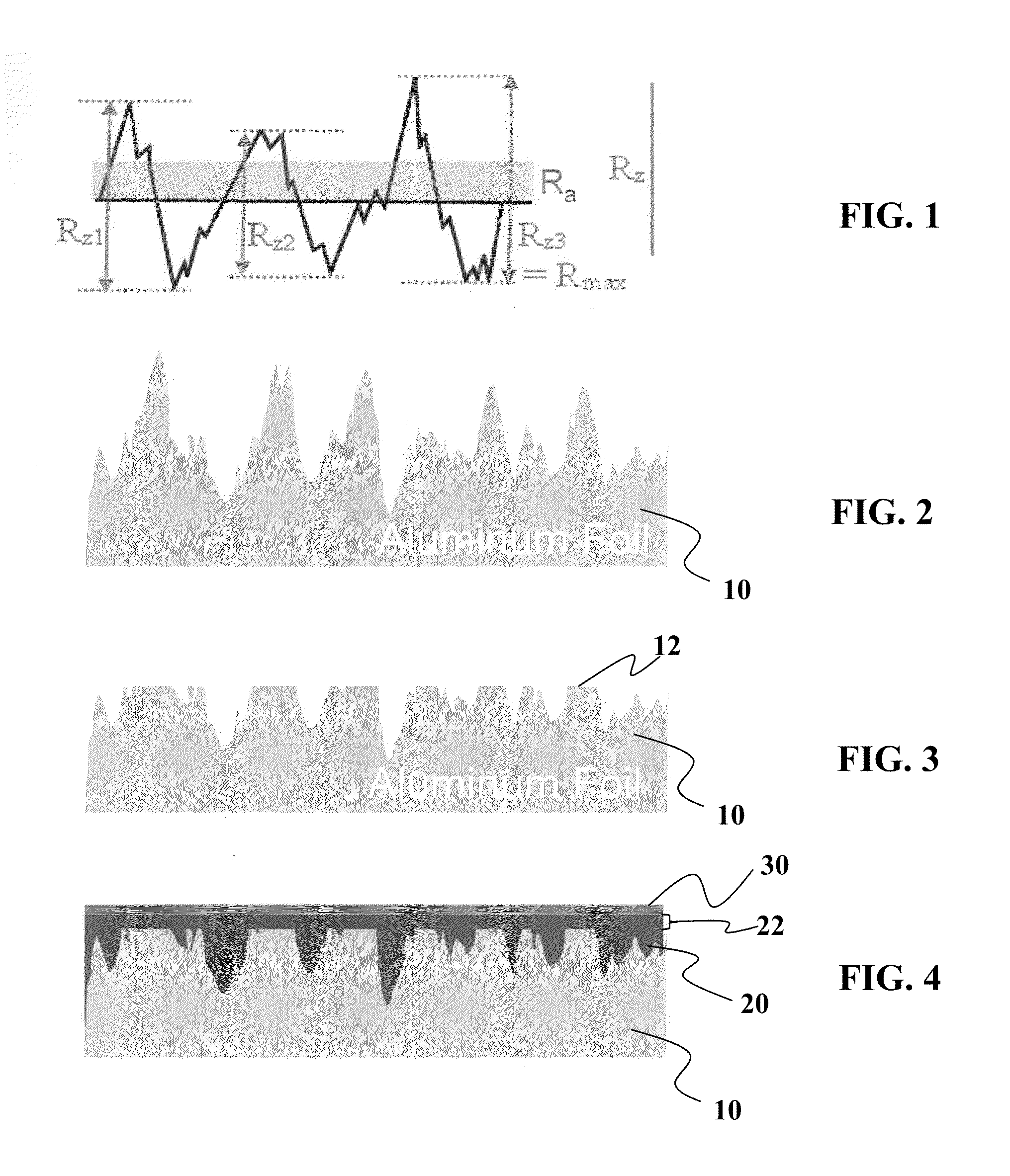
The poor quality is a based on the surface roughness which may be chemically brightened, and subsequently smoothed by reflow of material into the valleys.
Mechanical rolling is limited in the alloy or material that can be used due to the smoothening processes.
Chemical brightening also has limitations as to how smooth it can make the substrate.
Method used
View moreImage
Smart ImageViewing Examples

Examples
example i
[0045]An electrolyte is made up of the following composition:
[0046]5 g. molybdic anhydride
[0047]60 g. KOH
[0048]55 cc, NH4OH (28% NHs)
[0049]30 75CC.HC62H (87%) 15 cc.H2O
example 2
[0050]5 g. molybdie anhydride
[0051]50 g; KC2H3O2
[0052]10 . . . (glacial)
[0053]65-cc.:H2O
example 3
[0054]5 g. molybdic anhydride
[0055]74 cc. protrfonic acid. (HCsHsOz)
[0056]32 gm. (NH4>2COs
[0057]19 gm. KOH
[0058]28 cc. H2O
Login to View More PUM
| Property | Measurement | Unit |
|---|---|---|
| Ra | aaaaa | aaaaa |
| roughness | aaaaa | aaaaa |
| temperature | aaaaa | aaaaa |
Abstract
Description
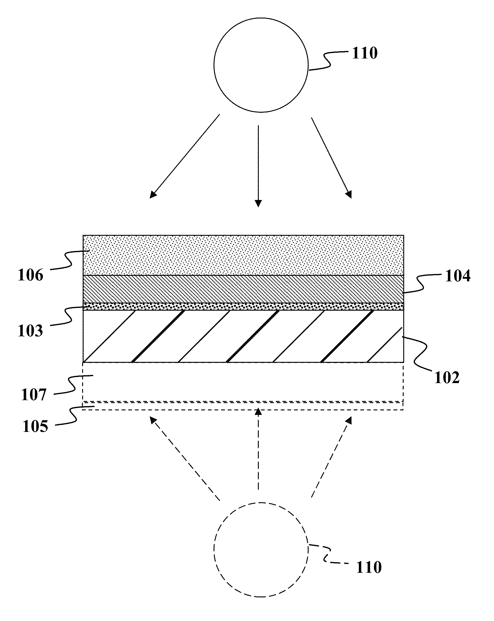
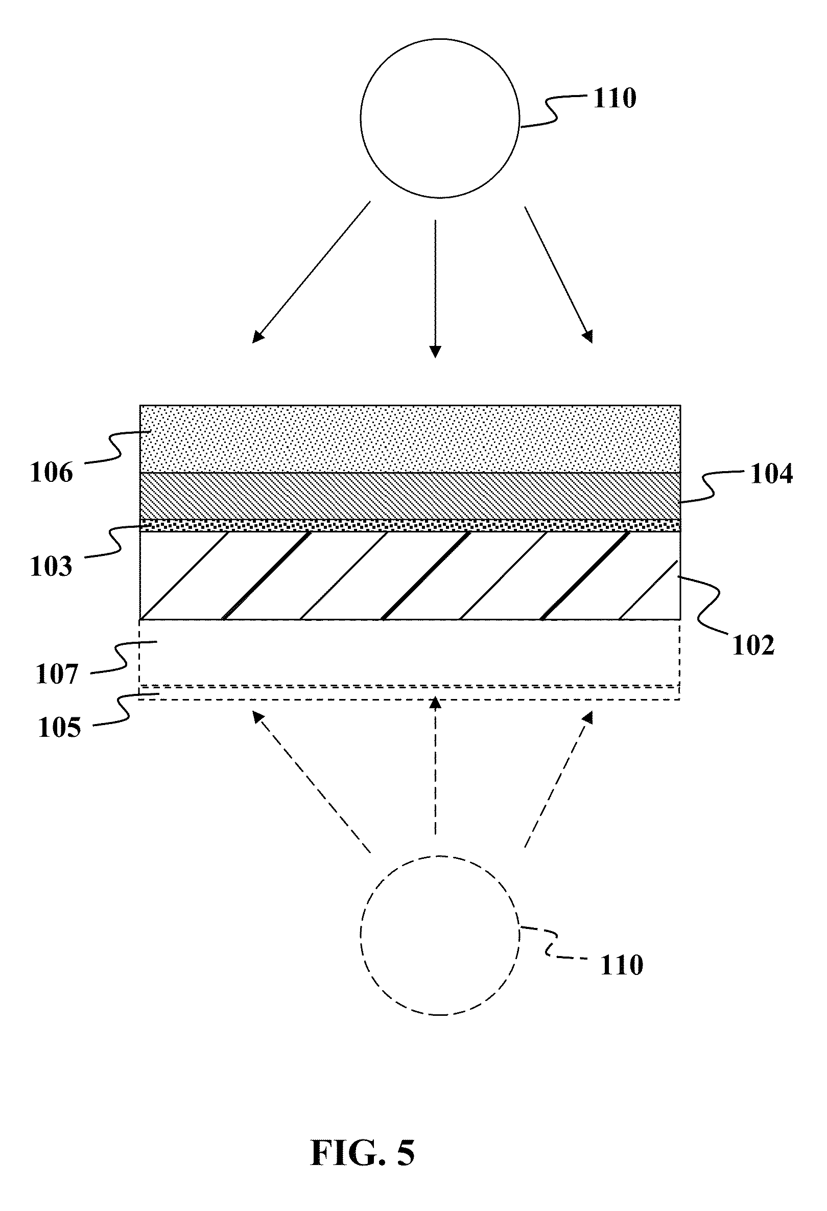
CROSS-REFERENCE TO RELATED APPLICATION[0001]This application claims the benefit of priority of U.S. Provisional Patent Application Ser. No. 61 / 221,517 filed Jun. 29, 2009 and fully incorporated herein by reference for all purposes.FIELD OF THE INVENTION[0002]This invention relates to substrates and more specifically to fabrication of solar cells on metal foil substrates.BACKGROUND OF THE INVENTION[0003]There is a need in the art for an efficient effective method of preparing rough substrates for use in solar cell manufacturing.SUMMARY OF THE INVENTION[0004]The disadvantages associated with the prior art are overcome by embodiments of the present invention. One of the main cost drivers is making it smooth with mirror finish requires different, expensive rolling process that also limits the number of materials which can be processed to such finish. Embodiments of the present invention address this issue.[0005]In one embodiment of the present invention, instead of using super quality s...
Claims
Login to View More Application Information
Patent Timeline
 Patent Type & AuthorityPatents(United States)
IPC IPC(8): B44C1/22
CPCH01L31/022425H01L31/0749H01L31/03928Y02E10/541Y02P70/50
InventorOETTING, WOLF
OwnerAERIS CAPITAL SUSTAINABLE IP