Measurement of binding kinetics with a resonating sensor

a resonator sensor and binding kinetic technology, applied in the field of measurement and testing, can solve the problems of long response time, limited diagnostic testing and analysis of chemical or biological materials at the point of need, and expensive remote or cumbersome laboratory equipment that costs thousands of dollars

Active Publication Date: 2013-04-02
QORVO BIOTECH LLC
View PDF108 Cites 65 Cited by
  • Summary
  • Abstract
  • Description
  • Claims
  • Application Information

AI Technical Summary

Benefits of technology

[0015]A number of advantages of the invention will become apparent to persons of skill in the relevant art based on the following description of the preferred embodiments.

Problems solved by technology

Still, a solution for diagnostic testing and analysis of chemical or biological materials at the point of need remains limited.
Diagnostic testing traditionally requires long response times to obtain meaningful data, involves expensive remote or cumbersome laboratory equipment that costs thousands of dollars located in a centralized laboratory, requires large sample sizes, utilizes multiple reagents, demands highly trained users, may require numerous steps, and / or involves significant direct and indirect costs.
For instance, in both the veterinary and human diagnostic markets, most tests require that a specimen be collected from the patient and sent to the laboratory, but the results are not available for several hours or days later.
As a result, the patient may leave the caregiver's office without confirmation of the diagnosis and the opportunity to begin immediate treatment.
Other problems related to portable devices include diagnostic results that are limited in sensitivity and reproducibility compared to in-laboratory testing.
Direct costs relate to the labor, procedures, and equipment required for each type of analysis.
Indirect costs partially accrue from the delay time before actionable information can be obtained, e.g., in medical analyses or in the monitoring of chemical processes.
Oftentimes, the sample must be refined prior to introduction into the assembly by the addition of buffer or removal of certain elements such as whole cells or other particulates, which can interfere with the accuracy of the measurements.
This refining step can be cumbersome and costly, making such measurements impractical for field applications.
One drawback of this approach is the introduced complexities and processing time requirements, which can result in expensive, error-prone, and time-consuming test results.
Another challenge faced by designers of resonant biosensors is in making quantifiable concentration measurements on highly concentrated samples.
In this case, although the sensor can operate as a simple detector of the presence of analyte, it cannot accurately measure the rate at which the analyte binds to the sensor, commonly referred to as binding kinetics.
Measurement of binding kinetics is needed for quantification of the concentration of the analyte, can be impossible to obtain with any suitable accuracy or repeatability in highly concentrated samples using conventional techniques.
Moreover, when analyte begins to bind to the resonator in significant quantity immediately from the moment that the resonant sensor is introduced to the sample, the instrument may not have the time to achieve its required stabilization prior to the taking of measurements, or to perform tuning of the resonator either before or after the taking of measurements, thereby further exacerbating the problem.

Method used


Image

  • Measurement of binding kinetics with a resonating sensor
  • Measurement of binding kinetics with a resonating sensor
  • Measurement of binding kinetics with a resonating sensor

Examples


Embodiment Construction

[0033]While this invention may be embodied in many different forms, there are described in detail herein specific preferred embodiments of the invention. This description is an exemplification of the principles of the invention and is not intended to limit the invention to the particular embodiments illustrated.

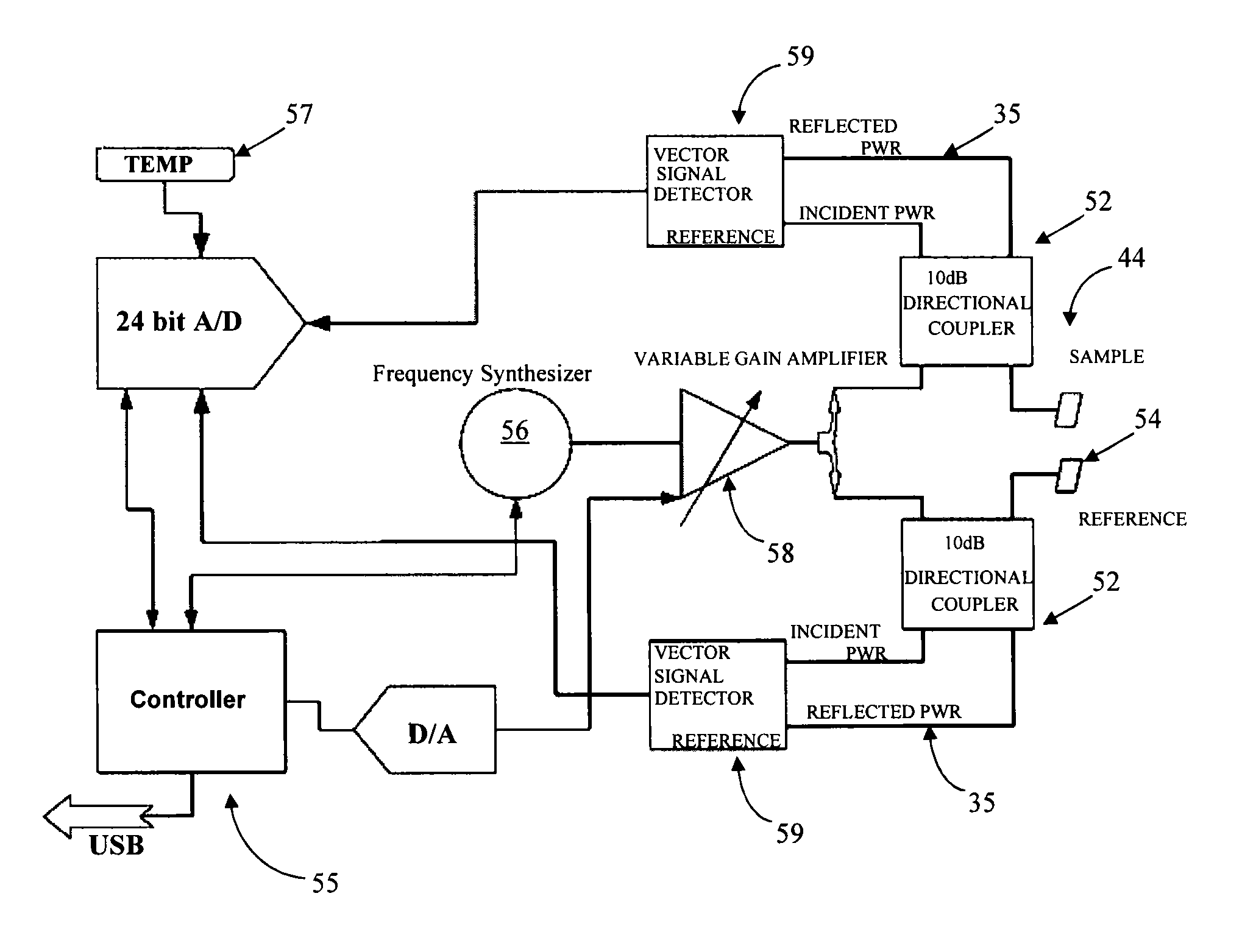
[0034]One aspect of the present invention is directed toward a simple, effective, cost-efficient, reliable, repeatable, sensor for resonance shift detection of chemical and / or biological materials that compensates for the variation of the unique resonant frequency in individual resonators. For the sake of brevity, these devices are referred to herein as biosensors, though it should be understood that they can be used to detect materials in samples other than biological samples. Resonance shift detection, in various embodiments, can be based on phase shift or frequency shift. One type of embodiment includes a sensor and resonance shift detection system that can compensate or a...


PUM

PropertyMeasurementUnit
resonant frequencyaaaaaaaaaa
diameteraaaaaaaaaa

Abstract

A subject material in a fluid sample is detected using a resonating sensor immersible in the fluid sample. Binding kinetics of an interaction of an analyte material present in the fluid sample are measured with the resonating sensor, which has binding sites for the analyte material. Prior to exposing the resonating sensor to the fluid sample, operation of the resonating sensor is initiated, producing a sensor output signal representing a resonance characteristic of the resonating sensor. Optionally, a reference resonator that lacks binding sites for the analyte is used to produce a reference output signal. Introduction of a fluid sample to the resonating sensor is automatically detected based on a characteristic change in the sensor output signal or a reference output signal. In response to the detecting of the introduction of the fluid sample, automated measurement of the binding kinetics are measured.

Description

PRIOR APPLICATION[0001]This application claims the benefit of U.S. Provisional Application No. 61 / 405,048 filed Oct. 20, 2010, entitled “RESONATOR OPERATING FREQUENCY OPTIMIZATION FOR PHASE-SHIFT DETECTION SENSORS,” the disclosure of which is incorporated by reference herein in its entirety.FIELD OF THE INVENTION[0002]The present invention relates to measurement and testing, and more specifically to piezoelectric resonator sensors and associated methods for diagnostic measuring or testing using the principle of a phase or frequency shift from an initial resonance point in response to exposure of the sensors to certain materials.BACKGROUND OF THE INVENTION[0003]There are a variety of instruments and measurement techniques for diagnostic testing of materials related to human health, veterinary medical, environmental, biohazard, bioterrorism, agricultural commodity and food safety. Still, a solution for diagnostic testing and analysis of chemical or biological materials at the point of...

Claims


Application Information

Patent Timeline
Patent Type & Authority Patents(United States)
IPC IPC(8): G01N33/566
CPCG01N33/54373G01N29/036G01N24/00G01N33/557G01N29/022G01N2291/0255G01N2291/0426G01N2291/0256
Inventor JOHAL, GAGANBIR SINGHHARMON, IAN ROBERTVAN DEUSEN, RICHARD ALLEN
Owner QORVO BIOTECH LLC
Why Eureka
Try Eureka