Battery assisted RFID system RF power control and interference mitigation methods

a battery-assist rfid and power control technology, applied in the field of radio frequency identification, can solve the problems of insufficient fully, prone to interference, and insufficient interference resistance of the machine governing passive tag operation, and achieve the effect of reliable interference resistance operation and efficient operation of the tag

Active Publication Date: 2013-04-02
ZEST LABS INC
View PDF15 Cites 47 Cited by
  • Summary
  • Abstract
  • Description
  • Claims
  • Application Information

AI Technical Summary

Benefits of technology

[0023]Systems, methods and devices are described for battery supported RFID systems that can both provide an intermediate level of performance between passive and Fully-Active systems, which provide for extension to active operation, and which for provide for reliable interference resistant operation in the presence of passive, battery assisted passive, and Fully-Active tags. This allows for flexibility across various system implementations, which enables an RFID infrastructure to efficiently operate with tags covering a wide range of possibilities, and where users can select the tag performance corresponding to a particular application.

Problems solved by technology

Simply adding tag sensitivity and greater range to the existing standardized passive RFID system design results in escalating difficulties.
These include the fact that only four session codes are highly interference prone in that it is insufficient to fully separate the readers that may be in range of a sensitive tag.
Also, the state machine governing passive tag operation is interference prone in that it was not designed to allow for rejecting reader commands from distant readers that more sensitive tags can hear.
Greater tag sensitivities, and the improved reader sensitivities that are needed to operate with more sensitive tags, are also subject to interference both within and from outside the RFID system.

Method used


Image

  • Battery assisted RFID system RF power control and interference mitigation methods
  • Battery assisted RFID system RF power control and interference mitigation methods
  • Battery assisted RFID system RF power control and interference mitigation methods

Examples


case 1

[0326]1. Accidental Wake-Up Due to Deliberately Transmitted Data.

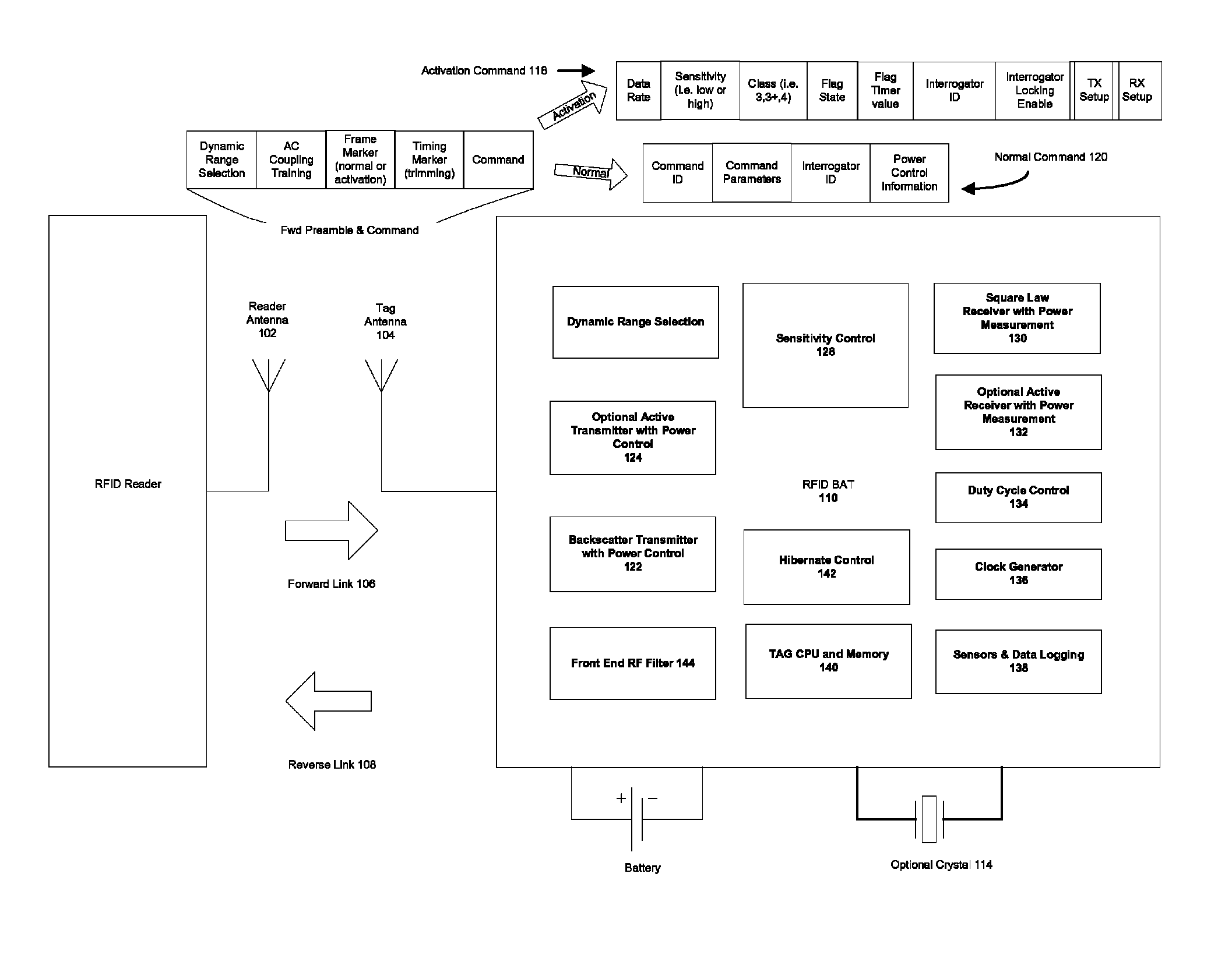
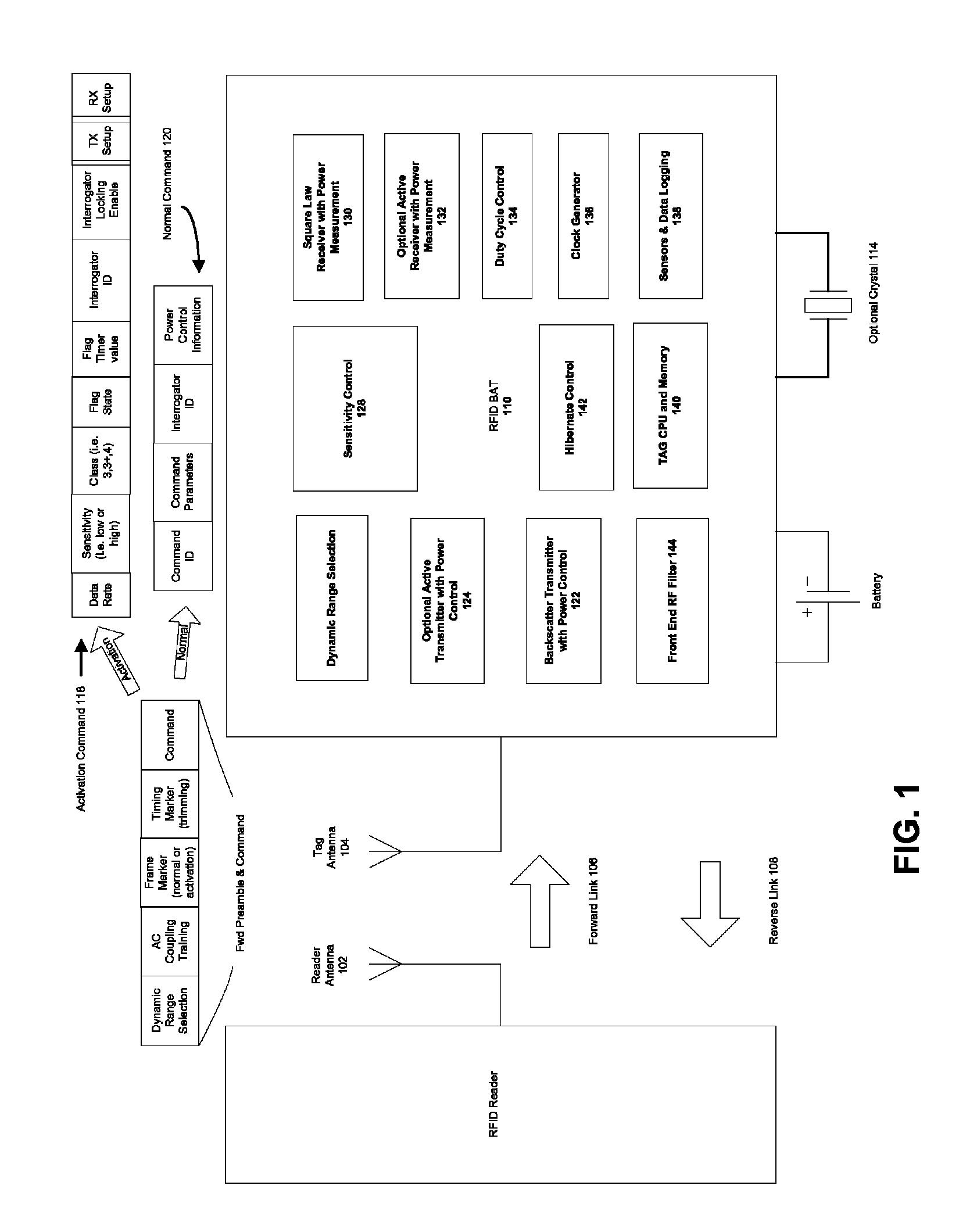
[0327]In certain embodiments of this invention, partial or entire correlation of the Activation and Frame Synchronization flag portion of the preamble is used to allow an early start to tag power-up sequencing, instead of waiting until the full Activation command is correctly received and decoded. This can reduce delay time before the tag is ready to begin normal mode operations. For example, it can take milliseconds to tens of milliseconds to power up a crystal oscillator and / or phase locked loop synthesizer for a Class 3 Plus or Class 4 tag, or to power up and lock a clock synthesizer for a microcontroller clock for a Class 3 tag. Accordingly, the PN sequence Activation Flag is designed so that this optional early start on power-up sequencing does not accidentally happen often enough to noticeably degrade battery life.

[0328]An analysis of this case makes use of the earlier development of the statistics under which t...


PUM


Abstract

The present invention discloses battery assisted RFID system RF power leveling methods that optimize the amount of transmitted power and interference from a reader in relation to the sensitivity of the RFID tags, their ranges from the reader, and the unique physics of the backscatter RFID radio link. These methods enhance system reliability when employing battery assisted RFID tags that operate with sensitive transistor based square law tag receivers and highly sensitive RFID readers intended to take advantage of outstanding tag sensitivity. Further enhancement is achieved via design of system command sets and tag state machine behavior that optimally support the power level operations, power level operations that span across tag hibernation and normal modes, and that otherwise control system interference. Embodiments of the present invention are also enhanced with receiver training and synchronizing methods suited to the high tag sensitivity and need for dynamic range state switching. These enhancements may employ pseudo-random sequence based receiver training, activation signaling, and frame synchronizing.

Description

BACKGROUND[0001]A. Field of the Invention[0002]The present invention relates generally to the field of Radio Frequency Identification (hereinafter, “RFID”) systems, and more particularly to advanced RFID systems which employ battery supported RFID tags allowing a higher degree of active behavior in tags.[0003]B. Background of the Invention[0004]The applications and importance of RFID technology has significantly grown in recent years due to a number of reasons including improvements in IC processes, RFID standards development, government allocation of increased spectrum for RFID, and growing awareness of the value of automated tracking of assets. During this growth, RFID systems have progressed from relatively simple, lower-frequency systems to include more complex systems that operate in the longer-range Ultra-High Frequency spectrum. The lower-frequency, generally inductively-coupled systems are usually referred to as Low Frequency (hereinafter “LF”, approximately 100-150 KHz) and...

Claims


Application Information

Patent Timeline
Patent Type & Authority Patents(United States)
IPC IPC(8): H04Q5/22
CPCG06K19/0701G06K19/0715G06K7/10039H04Q2213/13095
Inventor DACUS, FARRONVAN NIEKERK, JOHANNES ALBERTUSRODRIGUEZ, ALFONSO
Owner ZEST LABS INC
Why Eureka
Try Eureka