Wet scrubber tray

a scrubber tray and wet technology, applied in the direction of machines/engines, combustion air/fuel air treatment, separation processes, etc., can solve the problems of reducing the resistance of side stiffeners to vibration, wasting materials, etc., and achieves the effect of increasing the resistance to vibration-induced cracking, simple design and rugged construction

Active Publication Date: 2013-04-09
THE BABCOCK & WILCOX CO
View PDF20 Cites 15 Cited by
  • Summary
  • Abstract
  • Description
  • Claims
  • Application Information

AI Technical Summary

Benefits of technology

[0010]The present invention provides an improved wet scrubber perforated tray that provides increased resistance to vibration-induced cracking that is simple in design, rugged in construction, and economical to manufacture. The various features of the improved wet scrubber tray may be used singly or in any combination.
[0011]Accordingly, one aspect of the present invention is drawn to a modification of the sides of the tray to make the tray self supporting and to eliminate wastage of raw material. The original tray design had a high side and a low side that required the field welding of the low tray side to the high side of its neighboring tray to complete its support requirements. This construction required an extra shearing operation by the tray fabricator and the subsequent wastage of material. By providing two, equal height, side stiffeners, the tray stiffness is markedly increased. This change also eliminated the difficult field weld of the low side to the neighboring high side. In addition, the elimination of this field weld helped solve the cracking problem at Crack Site 1.
[0012]Another aspect of the present invention is drawn to the addition of an internal stiffener to the tray to make two intermediate stiffeners. The original design had one center stiffener that acted as a baffle for functional reasons, to stiffen the perforated bottom plate, and to provide a positive brace for the side stiffeners. The one problem with this design is that it still did not prevent the side stiffeners from warping. The addition of an internal stiffener eliminated the possibility of warping due to gas or spray buffeting. The previously mentioned aspect also worked to the benefit of this aspect by allowing for a shop weld to be applied at both ends of the intermediate stiffeners. The original tray design required field welding the center stiffener end to the neighboring tray high side. It is this field weld that provided the initiation point for the Crack Site 1 cracking. With certain changes in the specific design of the intermediate stiffeners, the intermediate stiffeners may be shop-installed or field-installed.

Problems solved by technology

This construction required an extra shearing operation by the tray fabricator and the subsequent wastage of material.
The one problem with this design is that it still did not prevent the side stiffeners from warping.

Method used


Image

  • Wet scrubber tray
  • Wet scrubber tray
  • Wet scrubber tray

Examples


Embodiment Construction

[0054]The natural circular frequency of a single degree of freedom component can generally be represented by the relationship:

ωn=√{square root over (k,m)}  (1)

[0055]where: ωn=circular frequency[0056]k=stiffness[0057]m=mass

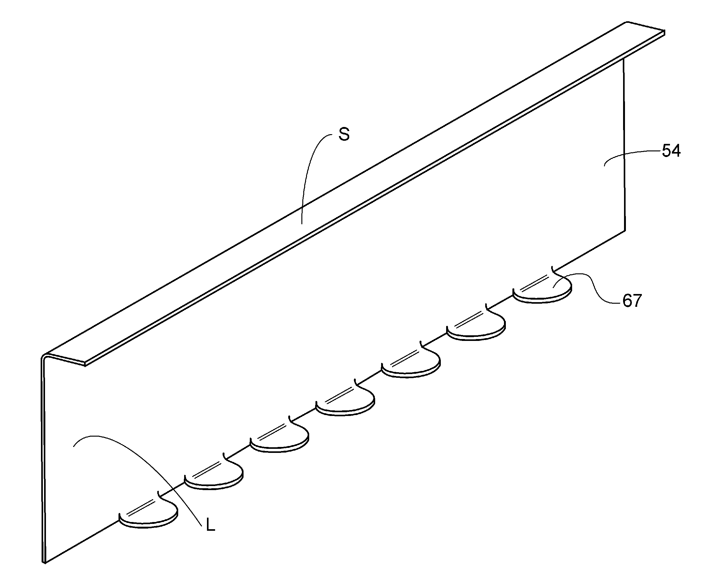
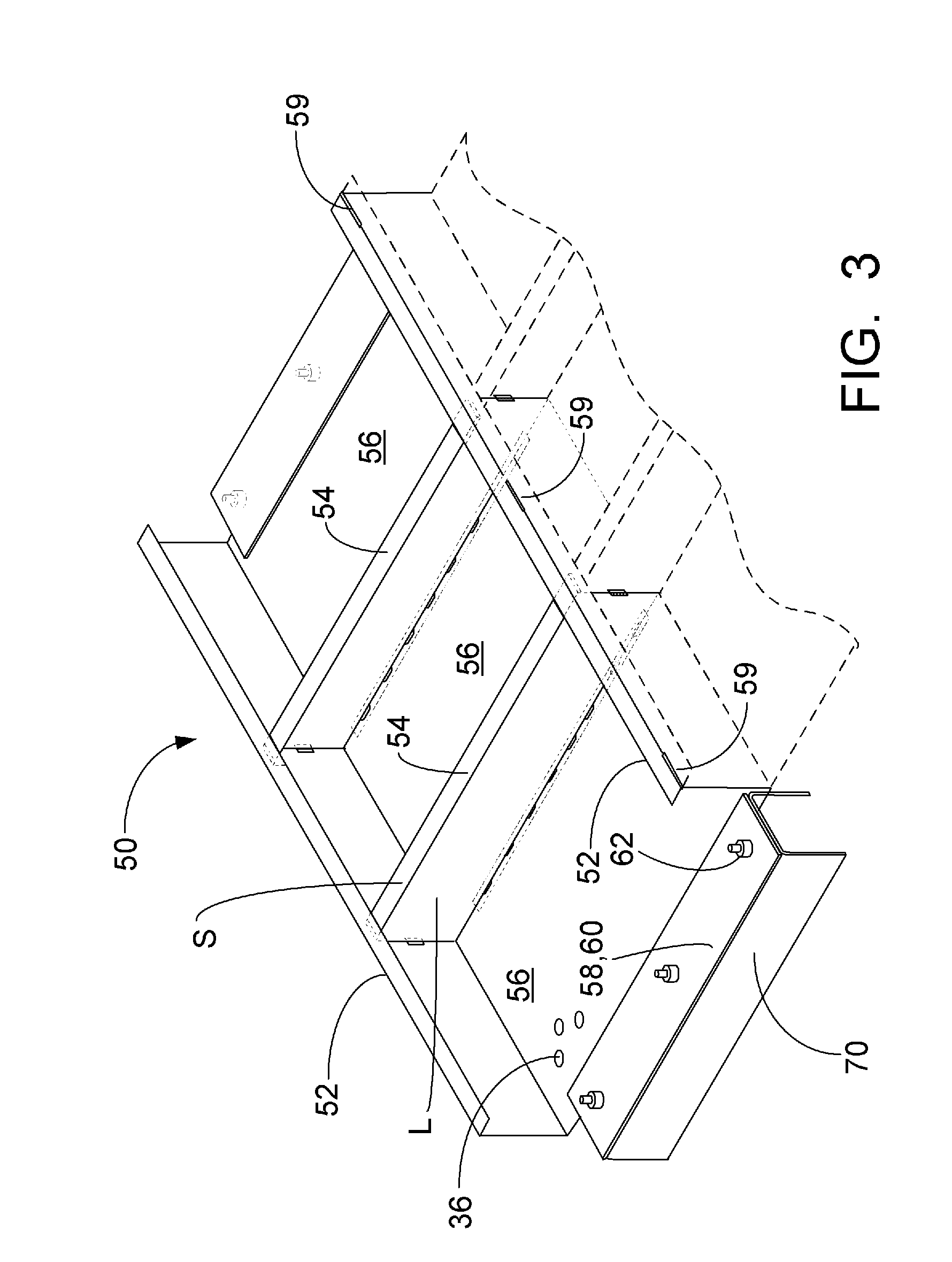
[0058]If the observed tray cracking is vibration-induced, the amplitude of the portions undergoing vibration is such that the stresses are exceeding the endurance limit, and the failures are due to fatigue. One way to reduce the amplitude of any component undergoing vibration at a given frequency is to increase the natural frequency of the component. Based upon the above relationship, increasing the stiffness-to-mass ratio of the component will increase the natural frequency. Thus, if the driving forces remain at the same frequency, stiffening the trays will reduce their likelihood to vibrate, thereby reducing the amplitude of vibration and the resulting flexural stresses experienced. The present invention thus provides several ways to increase the stiffness of the...


PUM

PropertyMeasurementUnit
angleaaaaaaaaaa
mass ratioaaaaaaaaaa
heightaaaaaaaaaa

Abstract

An improved wet scrubber tray provides increased resistance to vibration-induced cracking. The tray is self supporting to eliminate wastage of raw material, and additional internal stiffeners added to the tray make multiple intermediate stiffeners. The connection of the intermediate stiffeners to the perforated bottom plate is changed to eliminate the shop weld in the bottom plate. The holes in the perforated bottom plate are repositioned so that they are moved away from the boundaries of the tray to reduce their influence on boundary conditions. The thickness of the tray material may be increased to lower the vibratory stresses. The mechanism for holding the trays themselves within the spray absorber tower is changed so that the trays are now held down by plate material that is attached to the support grid, but not to the trays. Three field welds are applied to the sides of each tray to hold the trays in place relative to each other and are strategically placed to allow adjacent side stiffeners to act together as a composite section, thus increasing their strength. Elastomeric material such as neoprene is used at the tray-to-grid attachments to increase the damping of the system. Formed features in the trays such as single or multiple ribs, bosses, domes or dimples may also be provided to increase tray stiffness or influence wet scrubber performance.

Description

[0001]This application claims priority to U.S. Provisional Patent Application Ser. No. 61 / 061,900, filed Jun. 16, 2008.FIELD AND BACKGROUND OF THE INVENTION[0002]The present invention relates to methods and apparatus for obtaining counter-current gas-liquid contact, such as wet scrubbers which involve gas-liquid contact between flue gas containing sulfur oxides and a slurry or solution containing reactive materials as a chemical reacting absorbing medium. More particularly, the present invention is drawn to an improved wet scrubber tray construction and a gas-liquid contact apparatus employing same.[0003]Wet scrubber gas-liquid contact systems used for the removal of sulfur oxides (SOx) from flue gases produced from the combustion of fossil fuels are well known. See for example U.S. Pat. No. 4,263,021 to Downs et al., the text of which is hereby incorporated by reference as though fully set forth herein. Additional details of wet scrubber systems for SOx removal are provided in Chap...

Claims


Application Information

Patent Timeline
Patent Type & Authority Patents(United States)
IPC IPC(8): B01F3/04
CPCB01D3/324B01D53/78B01D3/326
Inventor JOHNSON, RONALD B.DUREIKO, RONALDPETERSON, DAVIDKIDWELL, J. JEFFREY
Owner THE BABCOCK & WILCOX CO
Why Eureka
Try Eureka