Imprint apparatus and article manufacturing method

a technology of printing apparatus and printing method, which is applied in the field of printing apparatus, can solve the problems of reducing the throughput of pattern printing apparatus, difficult alignment after pressing the mold, and prone to unfixed relative positions of the mold and the substrate, and achieves the effect of improving throughpu

Inactive Publication Date: 2013-04-09
CANON KK
View PDF12 Cites 5 Cited by
  • Summary
  • Abstract
  • Description
  • Claims
  • Application Information

AI Technical Summary

Problems solved by technology

In the case of pattern transfer by such a step and repeat method, if one transfer operation (to each shot) including pressing of a mold, exposing of light cure resin to light, and removal of the mold requires time, pattern transfer to the whole surface of a wafer (to all shots) also requires time, and this decreases the throughput of the pattern transfer apparatus.
The method disclosed in Japanese Patent Laid-Open No. 2007-266053, in which a mold and a substrate are relatively moved by a vibration generating mechanism, has a problem where the relative positions of the mold and the substrate are prone to be unfixed after the vibration generating mechanism is stopped.
The alignment after the pressing of the mold is not easy because a load is applied to the mold and the substrate.
Although alignment is not mentioned in Japanese Patent Laid-Open No. 2006-19464, the method disclosed therein has the same problem because a substrate and a mold are relatively moved after the pressing of the mold.

Method used


Image

  • Imprint apparatus and article manufacturing method
  • Imprint apparatus and article manufacturing method
  • Imprint apparatus and article manufacturing method

Examples


first embodiment

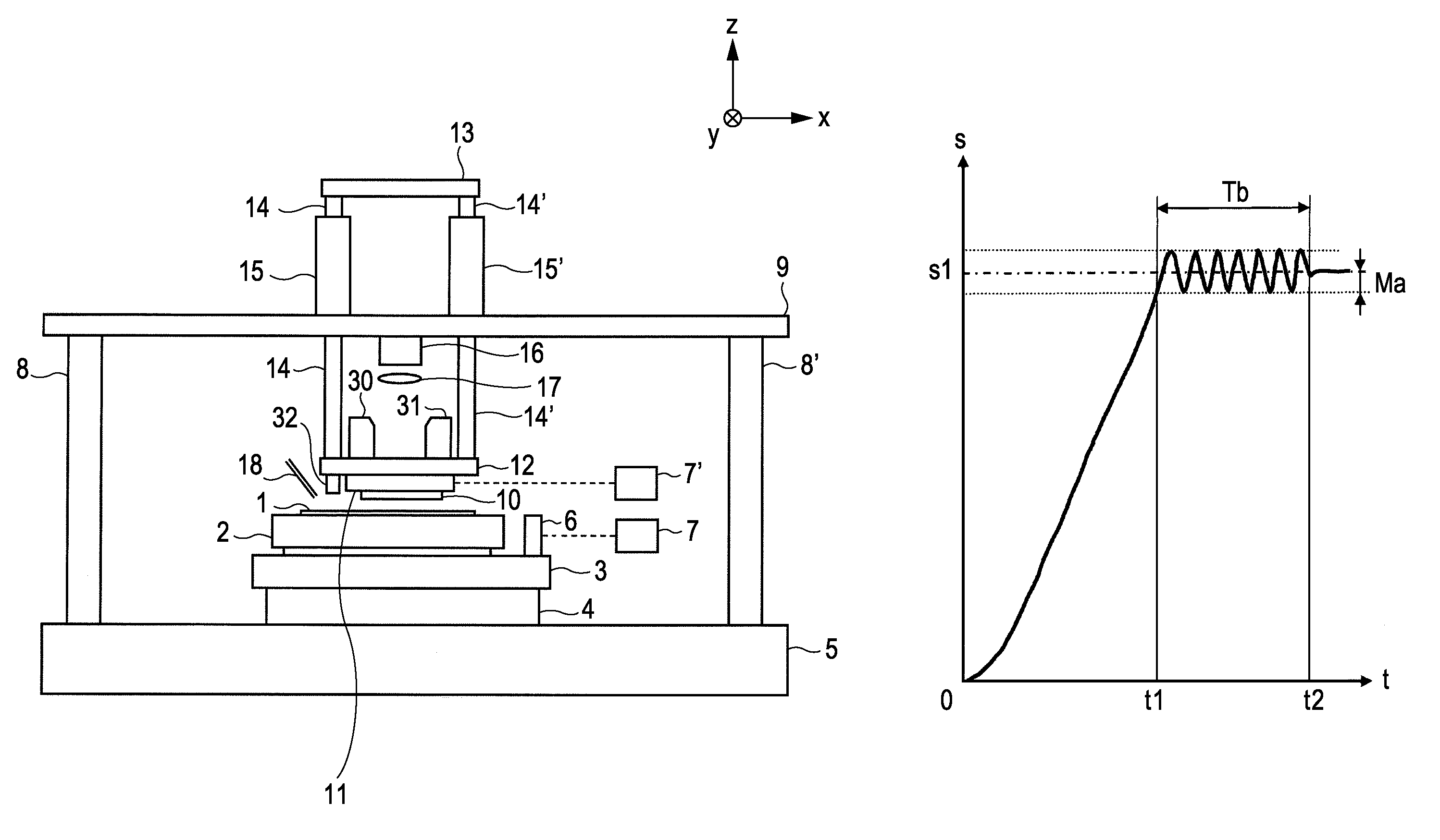
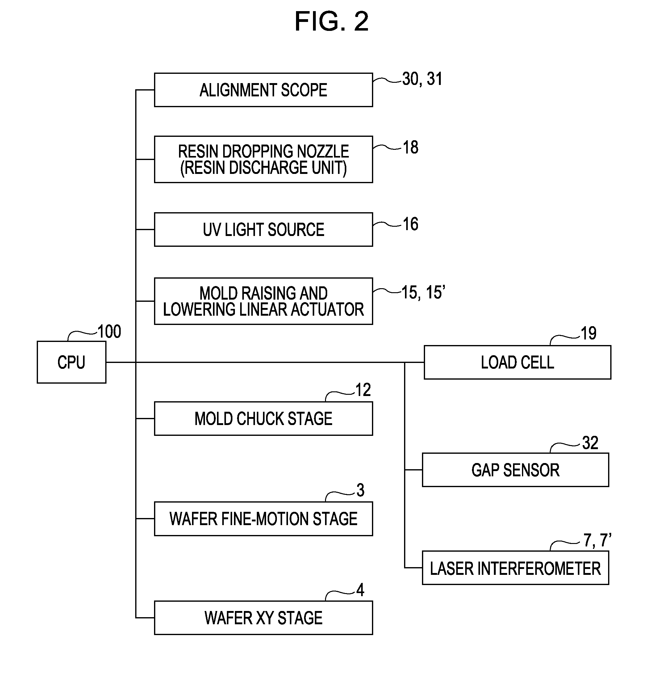
[0043]FIG. 4 is a flowchart of pattern transfer to a wafer 1 in the present invention and corresponds to step S107 of FIG. 11. This flowchart differs from the conventional flowchart of FIG. 15 in that steps (S31 and S32) are added in which the vibrating of the wafer stage 3, 4 (the fine-motion stage 3 and the XY stage 4) is started and stopped.

[0044]With reference to FIGS. 1, 2, and 4, a description will be given of the operation of an imprint apparatus according to a first embodiment of the present invention. Reference is made to FIG. 4. First, in step S1, the XY stage 4 is driven and the wafer chuck 2 on which a wafer 1 is placed is moved so that a place (shot) on the wafer 1 to which a pattern is transferred is located under the resin dropping nozzle 18. In step S2, light cure resin is dropped onto the target shot on the wafer 1 by the resin dropping nozzle 18.

[0045]Next, in step S3, the XY stage 4 is driven so that the plane of the shot is located opposite the pattern P2 of the ...

second embodiment

[0053]Next, with reference to FIGS. 7 and 8, a description will be given of the operation of a pattern transfer apparatus according to the present invention. FIG. 7 is a flowchart of pattern transfer to a wafer 1. This flowchart differs from the flowchart of FIG. 4 in that a step is added in which the vibration amplitude of the wafer stage is changed when the amount of pressing (the amount of lowering) of the mold 10 reaches a predetermined value. In FIG. 7, steps S1 to S4 (lowering of the mold chuck) are the same as those of FIG. 4.

[0054]The flow branches at step S41. In one of the branches, the determination whether or not the pressing force is appropriate (step S5) and the adjustment therefor (step S6) are the same as those of FIG. 4. In the other branch, in step S42, determination is repeated until the amount of lowering of the mold chuck 11 (the amount of pressing of the mold 10) reaches a predetermined value. When the amount of pressing of the mold 10 reaches the predetermined...

third embodiment

[0056]Next, with reference to FIGS. 9 and 10, a description will be given of the operation of a pattern transfer apparatus according to the present invention. FIG. 7 is a flowchart of pattern transfer to a wafer 1. This flowchart differs from the flowchart of FIG. 4 in that a step is added in which the vibration amplitude of the wafer stage is changed when the pressing force of the mold 10 reaches a predetermined value. In FIG. 9, steps S1 to S4 (lowering of the mold chuck) are the same as those of FIG. 4.

[0057]The flow branches at step S51. In one of the branches, the determination whether or not the pressing force is appropriate (step S5) and the adjustment therefor (step S6) are the same as those of FIG. 4. In the other branch, in step S52, determination is repeated until the pressing force of the mold 10 measured by the plurality of load cells 19 reaches a predetermined value. When the pressing force of the mold 10 reaches the predetermined value (YES in step S52), step S33 is p...


PUM

PropertyMeasurementUnit
frequencyaaaaaaaaaa
distanceaaaaaaaaaa
forceaaaaaaaaaa

Abstract

An imprint apparatus molds resin dispensed on a shot region of a substrate with a mold and forms a pattern of resin on the shot region. The apparatus includes a mold stage configured to hold the mold, a substrate stage configured to hold the substrate, a drive mechanism configured to change a relative positional relationship between the mold stage and the substrate stage in an X-Y plane that defines a coordinate of the shot region and a Z-axis direction perpendicular to the X-Y plane, and a controller. The controller is configured to control the drive mechanism so that the mold and the shot region perform relative vibration, in the X-Y plane, with respect to a relative position where the mold and the shot region align, and a distance between the mold and the shot region decreases in the Z-axis direction in parallel with the vibration, and the resin is molded by the mold.

Description

BACKGROUND OF THE INVENTION[0001]1. Field of the Invention[0002]The present invention relates to an imprint apparatus that molds resin dispensed on a shot region of a substrate and forms a pattern of resin on the shot region.[0003]2. Description of the Related Art[0004]Nanoimprinting is already known as an alternative to a method of forming a fine pattern on a semiconductor device using UV photolithography, X-ray lithography, or electron beam lithography. Nanoimprinting is a technique in which a mold on which a fine pattern is formed, for example, by electron beam exposure, is pressed against a substrate such as a wafer to which a resin material (resist) is applied, and thereby the pattern is transferred onto the resist.[0005]There are some types of nanoimprinting. A light cure method is one of them (M. Colburn et al., “Step and Flash Imprint Lithography: A New Approach to High-Resolution Patterning,” Proceedings of the SPIE's 24th International Symposium on Microlithography: Emergi...

Claims


Application Information

Patent Timeline
Patent Type & Authority Patents(United States)
IPC IPC(8): B29C43/22B29B17/00
CPCB82Y10/00B82Y40/00G03F7/0002B29C59/022
Inventor KAWAKAMI, EIGOKASUMI, KAZUYUKIINA, HIDEKI
Owner CANON KK
Why Eureka
Try Eureka