Orthopedic cast remover

a cast remover and orthodontic technology, applied in the field of medical cutting devices, can solve the problems of less than optimal performance, large dust, and high frequency oscillations, and achieve the effects of reducing noise, heat buildup, and minimizing the potential for patient skin conta

Inactive Publication Date: 2013-04-09
FELDMAN DAVID +2
View PDF17 Cites 9 Cited by
  • Summary
  • Abstract
  • Description
  • Claims
  • Application Information

AI Technical Summary

Benefits of technology

[0006]The present disclosure describes systems apparatuses and methods for making cast removal safer and easier. Under exemplary embodiments described below, a specially-configured saw should be able to cut through all layers of the cast in one pass while also minimizing the potential for patient skin coming into contact with the cutting surfaces. Additionally, the embodiments operate using a lower level of oscillation / velocity, resulting in reduced noise, heat buildup, as well as dust and debris production. Under normal operation, the disclosed saw replaces high velocity material removal methodologies of conventional designs with ones based on slow, high-force shearing.

Problems solved by technology

Several aspects of such a conventional design result in less than optimal performance.
As a result, portions of the cut away from the center of the blade application are often not fully separated and must be re-cut with the saw.
The high frequency oscillations produce uncomfortable noise levels and considerable dust when cutting.
Moreover, the use of an oscillating saw for cast removal creates a potential for iatrogenic injury and patient discomfort.
Burns and abrasions can occur from the heat created by frictional forces and direct blade contact.

Method used


Image

  • Orthopedic cast remover
  • Orthopedic cast remover
  • Orthopedic cast remover

Examples


Embodiment Construction

[0030]In the following detailed description of the invention, reference is made to the accompanying drawings which form a part hereof, and in which is shown, by way of illustration, specific embodiments in which the invention may be practiced. In the drawings, like numerals describe substantially similar components throughout the several views. These embodiments are described in sufficient detail to enable those skilled in the art to practice the invention. Other embodiments may be utilized and structural, electrical, and mechanical changes may be made without departing from the scope of the present invention.

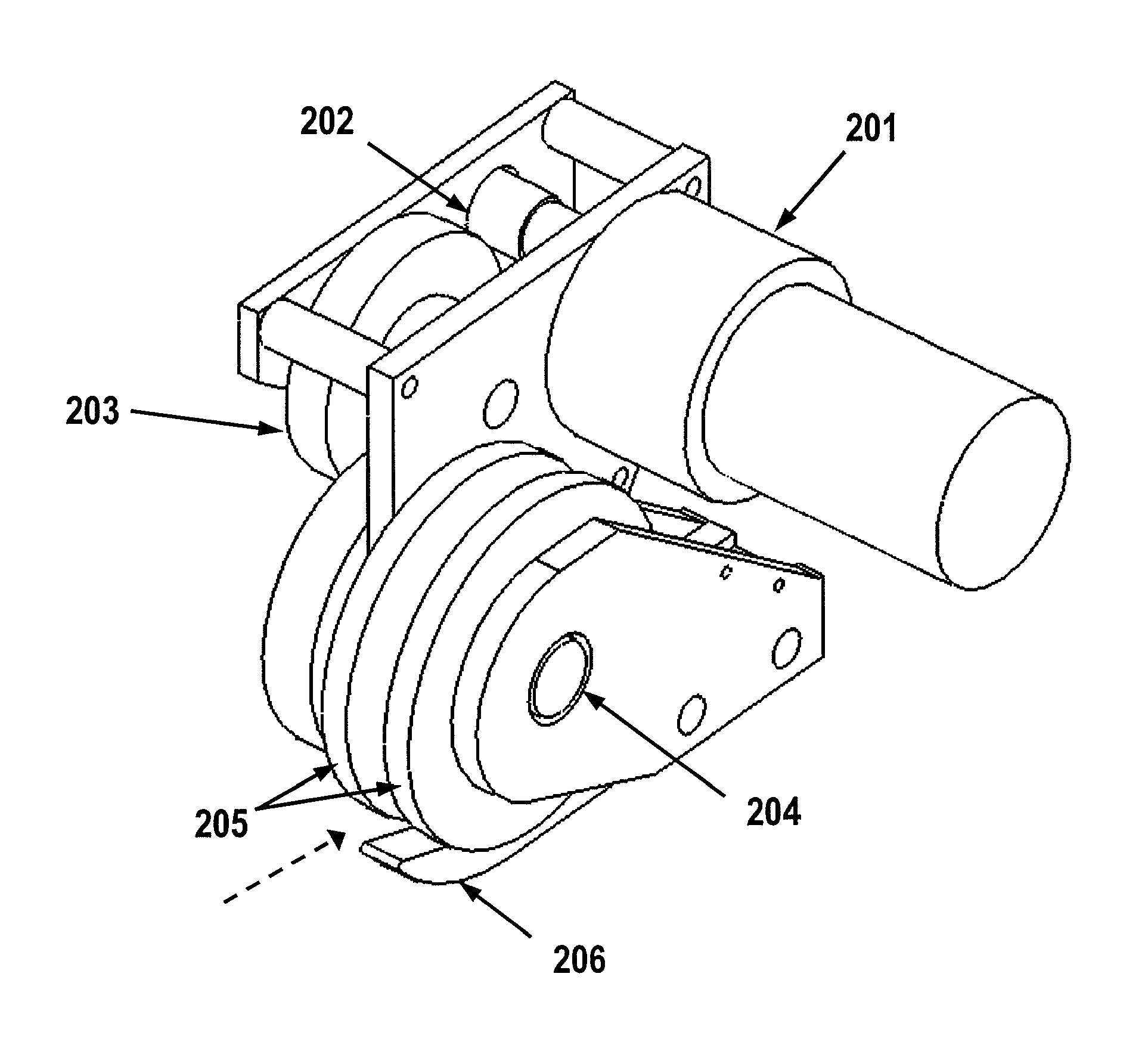
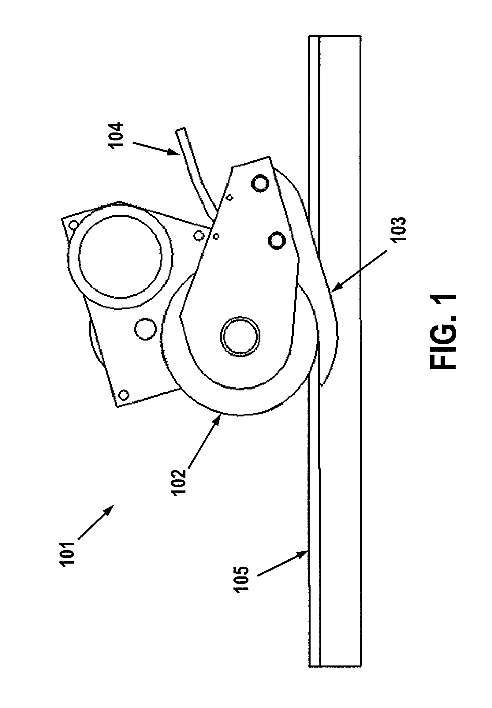
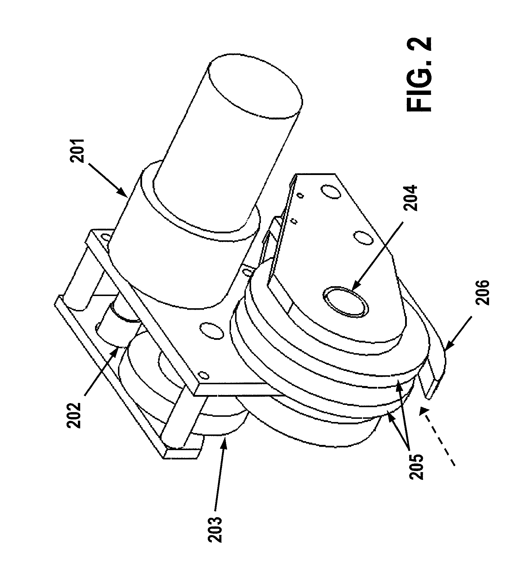
[0031]The present disclosure relates to a cutting device suitable for penetrating and removing a strip from the material to be cut. The device is specifically intended to cut fiberglass, plaster, and any other material used for orthopedic casts, though it is not limited to these materials. It is further designed to be used in the removal of orthopedic casts from a patient.

[0032...


PUM

PropertyMeasurementUnit
diameteraaaaaaaaaa
circumferential velocityaaaaaaaaaa

Abstract

Systems, apparatuses and methods are disclosed for an orthopedic cast remover. The cast remover includes a rotatable cutting assembly having first and second cutting wheel sandwiched between a smaller-sized hub, where the space between the first and second wheel defines a passage in which fractured material may pass. A shear is coupled to the cutting assembly and is positioned in the passage, where edges of the shear are configured to engage with each of the cutting wheels. During operation, rigid material, such as a cast shell, passes along a top surface of the shear and is fractured into a predetermined width at a point where the shear edges engage with the rotating cutting wheels. The fractured material is fed into the passage for easy removal.

Description

RELATED APPLICATIONS[0001]The present application claims priority to provisional application 61 / 110,012, titled “Orthopedic Saw”, filed Oct. 31, 2008, which is incorporated by reference in its entirety herein.TECHNICAL FIELD[0002]The present disclosure relates to systems, apparatuses and methods relating to medical cutting devices. More specifically, the disclosure relates, but is not limited to, cast removal systems that are designed for the removal of orthopedic casts generally applied for immobilization. Immobilization is considered essential for the proper healing of broken bones and other internal trauma.BACKGROUND INFORMATION[0003]Orthopedic casts typically consist of three layers. The outer layer, or the “shell”, is typically constructed of a quick drying bandage that hardens and becomes rigid upon drying. The shell layer provides the necessary rigidity and is typically made of either plaster, for its high formability, or fiberglass, for its faster drying time and lighter con...

Claims


Application Information

Patent Timeline
Patent Type & Authority Patents(United States)
IPC IPC(8): A61F5/04
CPCA61F15/02B26D1/14Y10T29/49826B26D2001/0066B26D7/20B27B19/00
Inventor BAKER, RUSSELL
Owner FELDMAN DAVID
Why Eureka
Try Eureka