Casting composite ingot with metal temperature compensation

a temperature compensation and composite metal technology, applied in the direction of casting parameters measurement/indication devices, manufacturing tools,foundry moulding apparatus, etc., can solve the problems of metal-metal interface failure, adversely affecting the cast product, and molten metal flow into the casting mold can be hindered

Active Publication Date: 2013-04-16
NOVELIS INC
View PDF11 Cites 3 Cited by
  • Summary
  • Abstract
  • Description
  • Claims
  • Application Information

AI Technical Summary

Benefits of technology

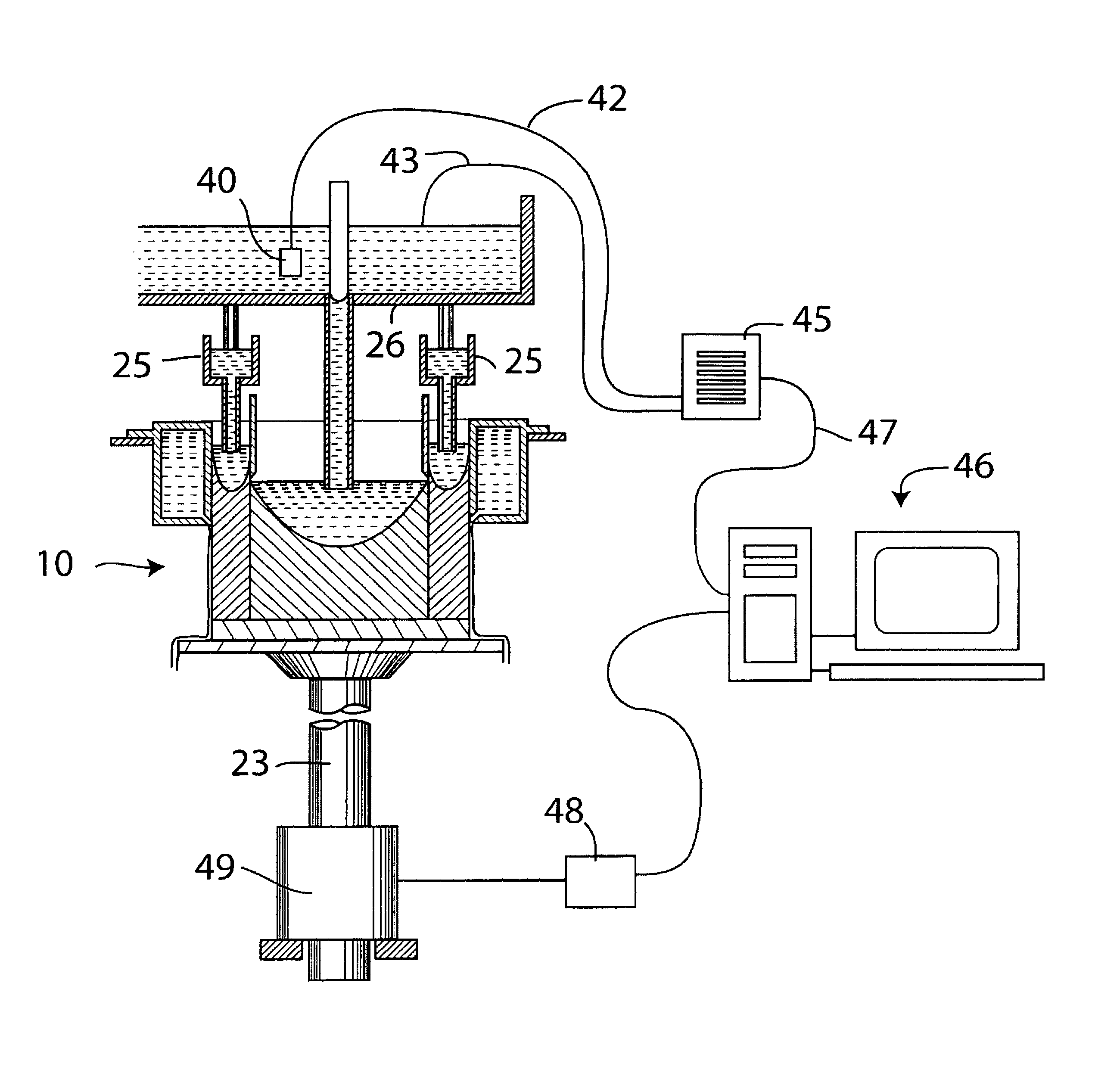
[0010]One exemplary embodiment of the invention provides a method of direct chill casting a composite metal ingot, which involves sequentially casting at least two metal layers to form a composite ingot by supplying streams of molten metal to at least two casting chambers within a casting mold of a direct chill casting apparatus, monitoring an inlet temperature of one or more of the streams of molten metal at a position adjacent to an inlet of a casting chamber fed with the stream, and comparing the monitored temperature with a predetermined set temperature for the stream to detect a temperature difference from the set temperature, and adjusting a casting variable that affects molten metal temperatures entering or within the casting chambers by an amount based on the one or more of the detected temperature differences to minimize adverse casting effects caused by the one or more temperature differences.
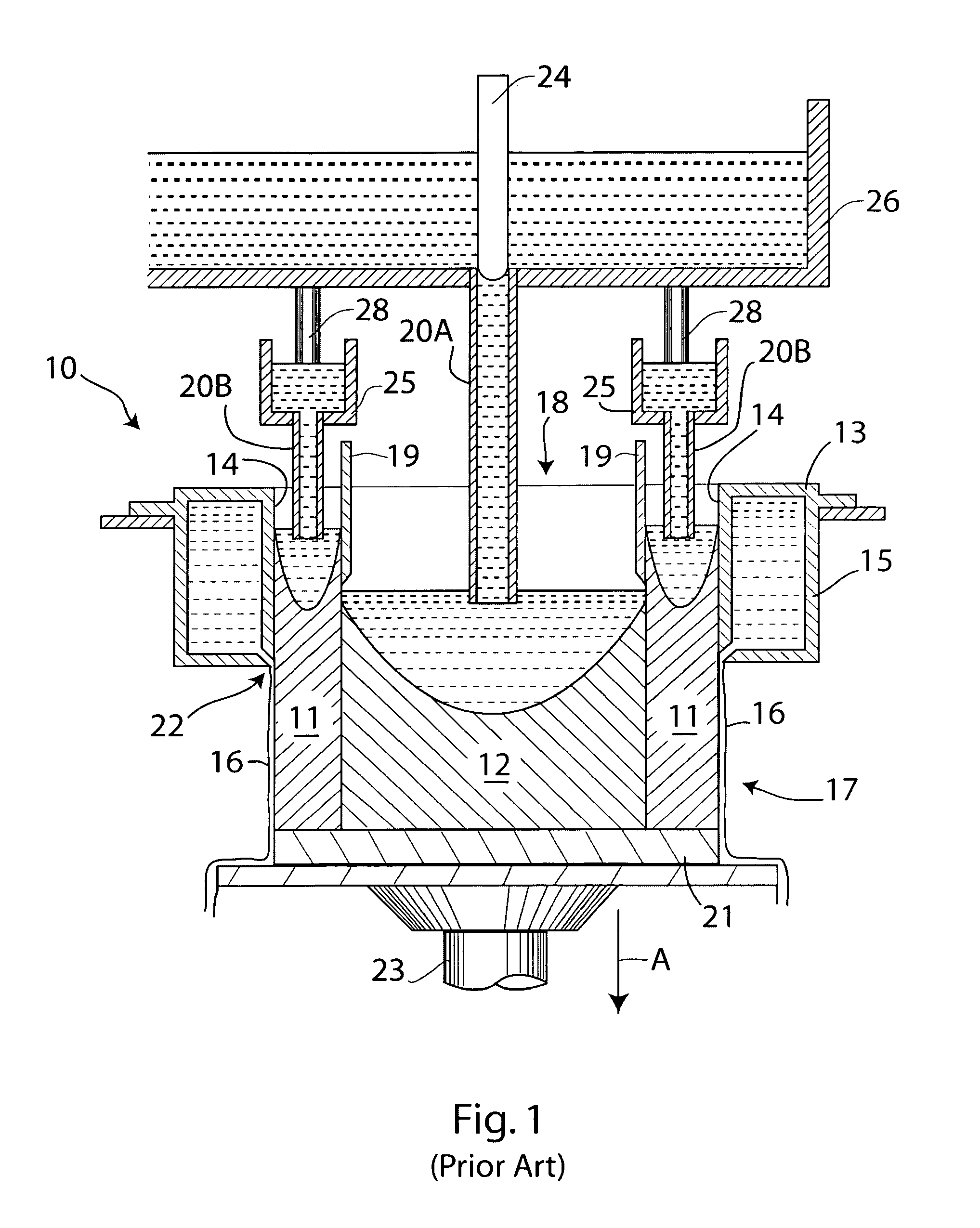
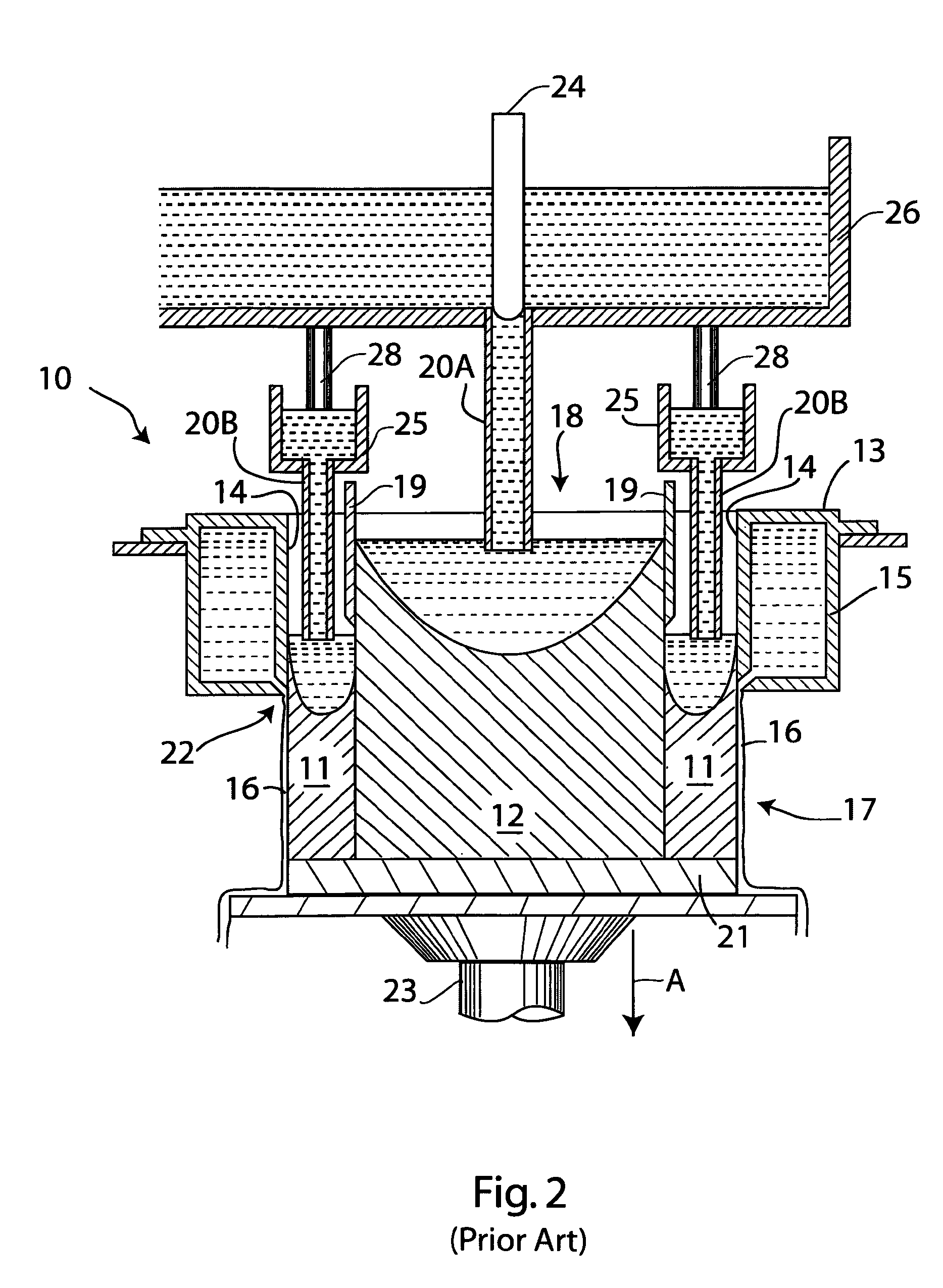
[0015]The rate of cooling of the metal streams within the mold (i.e. either increased cooling or decreased cooling) may be varied by adjusting the cooling of chilled divider walls used to separate the chambers of the mold. Typically, the divider walls are made of a heat-conductive metal chilled by water flowing through tubes held in physical contact with the divider walls. Adjusting the rate of flow of the cooling water (and / or its temperature) increases or decreases the amount of heat extracted from the divider wall, and thus increases or decreases the heat extracted from, and temperature of, molten metal in contact with the divider wall. Thus, the temperature of the molten metal in contact with the divider wall is adjusted within the mold itself. The metal in contact with the divider wall eventually forms part of the metal interface between adjacent metal layers and thus the amount of cooling the metal receives directly affects the physical characteristics of the metal at the interface (i.e. the temperature and thickness of a semi-solid metal shell formed from the molten metal at the interface). Increasing the rate of flow of water through the tubes attached to the divider wall thus increases the rate of cooling of the molten metal in contact with the divider wall, and thus compensates for a temperature of the molten metal above the intended temperature (set point) as it enters the mold. Conversely, a decrease in the rate of flow of cooling water compensates for a temperature of the molten metal below the set point.
[0016]Similarly, the rate at which cooling water is applied to the exterior of the ingot emerging from the mold may increase or decrease the temperature of the metal within the mold because heat is conducted from the metal within the mold along the ingot to the point where heat is withdrawn by the applied external cooling water. Thus, increasing the flow of cooling water (and / or its temperature) produces an increased cooling effect on the molten metal within the mold (thus compensating for temperatures above the set point), and decreasing the flow of cooling water produces a relative reduction of cooling (compensating for temperatures below the set point).
[0017]Adjustment of the surface heights of the metal pools within the mold chambers has the effect of varying the metal temperature at the interface where the metals contact each other because greater metal depth within a casting chamber increases the time during which the molten metal is in contact with the chilled mold walls and dividers, and shallower metal depth decreases the cooling time. The metal heights can be adjusted by changing the rate at which molten metal is introduced into the mold chambers, e.g. by moving valves or “throttles” (usually refractory rods) within the metal supply apparatus. Thus, increased metal depth compensates for temperatures above the set point, and decreased metal depth compensates for temperatures below the set point.
[0018]One objective of the adjustment of the casting variables is to prevent rupture, collapse or other failure of the interface where the metals of the cast layers first meet. In sequential casting, a newly-formed metal surface made of semi-solid metal is employed as a support on which molten metal for an adjacent layer is cast and cooled. The layer of semi-solid metal is formed as an outer shell around a core of still molten metal, so the shell should be thick enough to avoid rupture or collapse when contacted with the molten metal from the other cast layer. The thickness of the shell is dependent on the time during which the metal layer was cooled, particularly by the divider walls. Furthermore, the temperature of the semi-solid layer should be such that it is not raised into the molten range of temperatures when contacted with the molten metal of the other layer, otherwise the interface may again be subject to rupture or collapse. Thus, the generation of a viable casting interface is very much dependent on the time of cooling and lowest temperature of the first metal to be cast at the point where the cast metals first meet and fully solidify. It is therefore one objective to make adjustments to a casting variable that affects this cooling time and temperature to compensate for fluctuations in the inlet temperatures of the molten metals around the predetermined set point. Another objective of the adjustment of casting variables is to compensate for poor metal flow or the introduction of solid or semi-solid metal artifacts into the casting chambers caused by undue cooling of the metal being introduced. A variable such as casting speed can be used for such compensation as will be apparent from the description below.
[0019]A particular feature of the exemplary embodiments is that variations of the inlet temperatures of at least two metal streams are compensated for by the adjustment of just one casting variable, e.g. casting speed, that affects all of the metal layers. The inventors have found that, within predetermined ranges of variation from the set temperatures for the metal streams, a degree of heat transfer takes place across the metal-metal interface to equalize or minimize the effects of the temperature differences of the various metal streams. For example, if the cladding metal is too hot by an amount greater than the core metal, but is still within the predetermined range, a casting speed reduction based on the temperature of the core metal will stabilize the metal-metal interface because the super-heat of the cladding layer will be transferred in part to the core layer and will therefore not have the adverse effect otherwise anticipated. Additional cooling of the cladding metal is therefore not required. It is also possible to adjust the casting variable based on a summation or average of the excess inlet temperatures of both or all of the molten metal streams.

Problems solved by technology

If one or more of the metal streams is too hot, rupture or other kind of failure of the metal-metal interface where the metals first come into contact may occur as the ingot is being formed.
On the other hand, if one or more of the metal streams is too cold, the flow of molten metal into the casting mold can be hindered due to partial or complete freezing of the metal in downspouts or distribution troughs used for conveying the metals to the casting mold.
Additionally, in such cases, pre-solidified material may be delivered to the casting mold itself which adversely affects the cast product.
While the apparatus is generally optimized to deliver metals to the mold at desired temperatures (referred to as a “set point” for a particular metal), it is not always easy in practice to maintain the desired temperatures due to environmental factors and unexpected operational variations.
While the above-mentioned International patent publication to Anderson et al. discloses a basic process for co-casting multiple layers to form composite ingots, the problems caused by variations of input temperatures are not discussed or disclosed and no solutions are discussed.

Method used


Image

  • Casting composite ingot with metal temperature compensation
  • Casting composite ingot with metal temperature compensation
  • Casting composite ingot with metal temperature compensation

Examples


examples

[0055]Examples of the way in which the casting speed can be adjusted, and on which an associated computer algorithm was based, are shown in FIGS. 6 and 7, where FIG. 6 shows the situation for a high clad casting arrangement and FIG. 7 shows the situation for a low clad casting arrangement. FIG. 6 involved the casting of a core of proprietary AA5000 series aluminum-based alloy containing about 6% by weight Mg, with two cladding layers of another proprietary AA5000 series aluminum-based alloy containing about 1% by weight Mg. FIG. 7 involved the casting of a core of AA3000 series aluminum-based alloy and two cladding layers of proprietary AA4000 series aluminum-based alloy, which resulted in an ingot later rolled to produce a brazing sheet product. Although the measured temperatures and adjusted casting speeds are not shown in these drawings, they varied within the indicated limits. That is to say, an adjustment of the casting speeds resulting from variations of the inlet temperatures...


PUM

PropertyMeasurementUnit
temperaturesaaaaaaaaaa

Abstract

An exemplary embodiment of the invention provides a method of direct chill casting a composite metal ingot. The method involves sequentially casting two or more metal layers to form a composite ingot by supplying streams of molten metal to two or more casting chambers within a casting mold of a direct chill casting apparatus. Inlet temperatures of one or more of the streams of molten metal are monitored at a position adjacent to an inlet of a casting chamber fed with the stream, and the inlet temperatures are compared with a predetermined set temperature for the stream to determine if there is any difference. A casting variable that affects molten metal temperatures entering or within the casting chambers (e.g. casting speed) is then adjusted by an amount based on the difference of the compared temperatures to eliminate adverse casting effects caused by the difference of the inlet temperature and the set temperature. Preferably an adjustment is selected that causes the monitored temperature to approach the set temperature. Another exemplary embodiment provides equipment for operation of the method.

Description

CROSS-REFERENCE TO RELATED APPLICATION[0001]This application claims the priority right of prior co-pending U.S. provisional patent application Ser. No. 61 / 337,611 filed on Feb. 11, 2010 by applicants named herein. The entire contents of application Ser. No. 61 / 337,611 are specifically incorporated herein by this reference for all purposes.BACKGROUND OF THE INVENTION[0002]I. Field of the Invention[0003]This invention relates to the casting of composite metal ingots by sequential direct chill casting. More particularly, the invention relates to such casting in which compensation is made for variations of the input temperatures of molten metals being cast.[0004]II. Background Art[0005]It is desirable for many purposes to cast metal ingots made of two or more metal layers. For example, rolled products produced from such ingots may be formed with a metal coating layer on one or both sides of a core layer in order to provide specific surface properties that may differ from the bulk proper...

Claims


Application Information

Patent Timeline
Patent Type & Authority Patents(United States)
IPC IPC(8): B22D11/00B22D11/16
CPCB22D11/007B22D2/006B22D11/22B22D11/202B22D11/182B22D15/00B22D7/02
Inventor WAGSTAFF, ROBERT BRUCESINDEN, AARON DAVIDBISCHOFF, TODD F.BALL, ERICMCDERMOTT, JEFF
Owner NOVELIS INC
Why Eureka
Try Eureka