Aircraft actuator hydraulic system

a technology of hydraulic system and actuator, which is applied in the direction of power amplification, transportation and packaging, and parallel arrangement of servomotors, etc. it can solve the problems of significant constraint on continuous running time and oil replacement time associated with oil degradation, and increase the overall temperature of the hydraulic system, so as to suppress the increase in the temperature of the backup hydraulic pump

Active Publication Date: 2013-04-16
NABLESCO CORP
View PDF18 Cites 11 Cited by
  • Summary
  • Abstract
  • Description
  • Claims
  • Application Information

AI Technical Summary

Benefits of technology

[0008]In view of the foregoing circumstances, it is an object of the present invention to provide an aircraft actuator hydraulic system that can drive actuators even in the case of a loss or degradation in the function of the aircraft central hydraulic power source, can prevent an increase in the size and the weight of the system, and can suppress an increase in the overall temperature of the system and the temperature of the oil used.
[0018]With this configuration, the first backup hydraulic pump and the first electric motor are installed inside the first wing, and the second backup hydraulic pump and the second electric motor are installed inside the second wing. Accordingly, the aircraft actuator hydraulic system is installed in a region close to the actuators, making it possible to realize a further reduction in the size and the weight of the hydraulic system. Moreover, the hydraulic system having this configuration is configured such that the inlet port opening / closing portion and the exhaust port opening / closing portion operate to open the inlet port and the exhaust port, thus making it possible to supply the low-temperature air outside the first wing and the second wing into at least one of the first wing and the second wing and discharge the high-temperature air inside at least one of the first wing and the second wing to the outside of that wing. Accordingly, the heat generated from at least one of the first and second backup hydraulic pumps and at least one of the first and second electric motors of the hydraulic system can be removed by the air flowing in from the inlet port to the exhaust port, thereby cooling the hydraulic system. That is, the heat generated in the hydraulic system can be released directly to the atmosphere outside the wings. With the hydraulic system having this configuration, the inlet port and the exhaust port are opened if both of the first and second backup hydraulic pumps are activated when a loss or degradation in the function of both of the first and second aircraft central hydraulic power sources occurs. Therefore, even in such a case where the oil coolers of the aircraft central hydraulic power sources cannot be used when a loss or degradation in the function of both of the first and second aircraft central hydraulic power sources occurs, it is possible to suppress an increase in the overall temperature of the hydraulic system and an increase in the temperature of the oil used. Furthermore, with the hydraulic system having this configuration, the inlet-side drive mechanism that drives the inlet port opening / closing portion to be opened and closed and the exhaust-side drive mechanism that drives the exhaust port opening / closing portion to be opened and closed operate in accordance with a command signal from the controller that controls the operation of the first and second backup hydraulic pumps. Accordingly, it is possible, by effectively utilizing the controller that controls the operation of the first and second backup hydraulic pumps, to achieve a control configuration that can open the inlet port and the exhaust port in response to the operation status of the first and second backup hydraulic pumps, without adding an extra control apparatus.

Problems solved by technology

This tends to cause an increase in the overall temperature of the hydraulic system, and also tends to cause an increase in the temperature of the oil (working fluid) that is supplied as the pressure oil from the pump to the actuator and that is circulated between the pump and the actuator.
Accordingly, there is a significant constraint on the continuous running time and the time for oil replacement associated with oil degradation.
However, this may lead to an increase in the size and the weight of the hydraulic system.

Method used


Image

  • Aircraft actuator hydraulic system
  • Aircraft actuator hydraulic system
  • Aircraft actuator hydraulic system

Examples


first embodiment

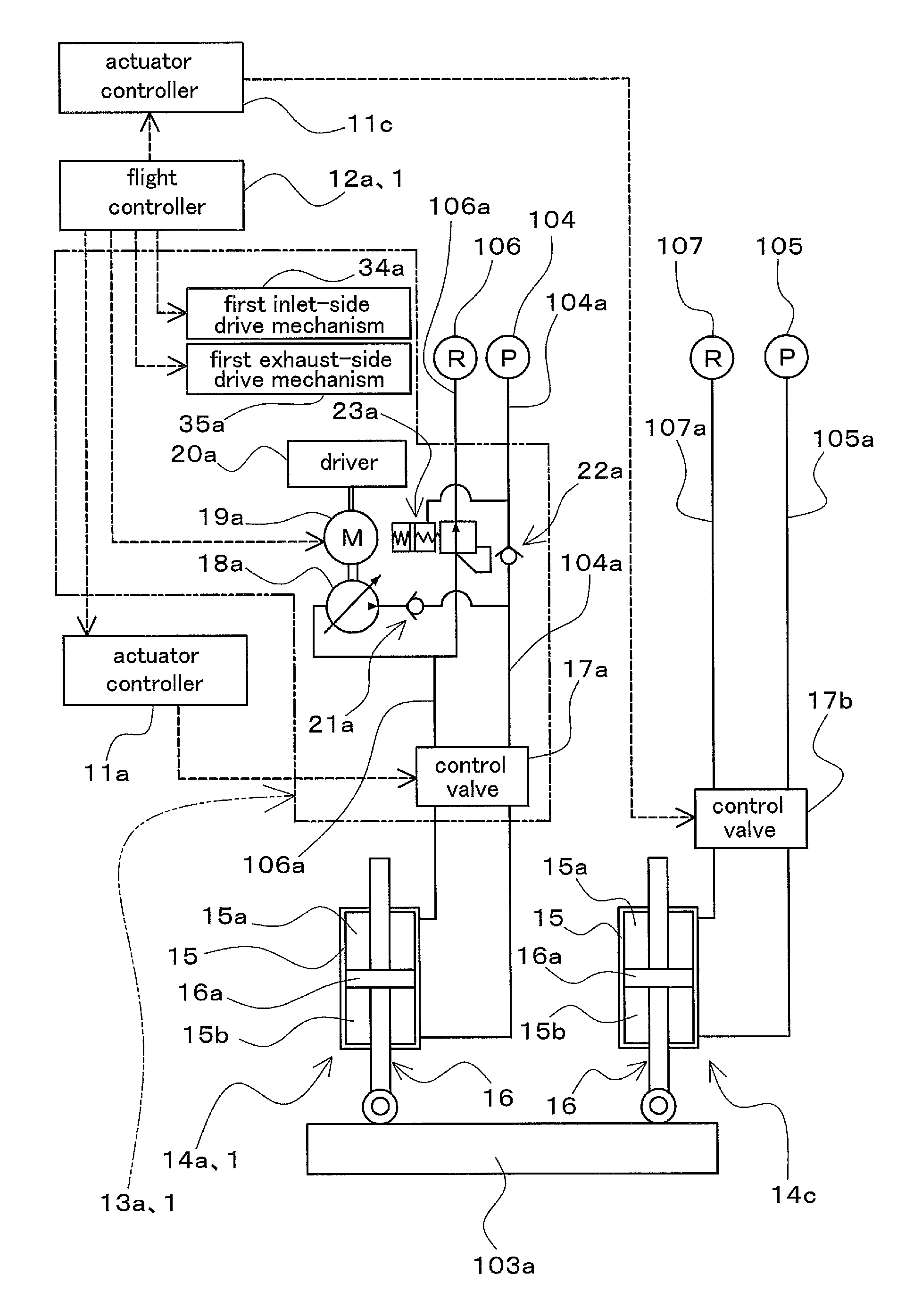
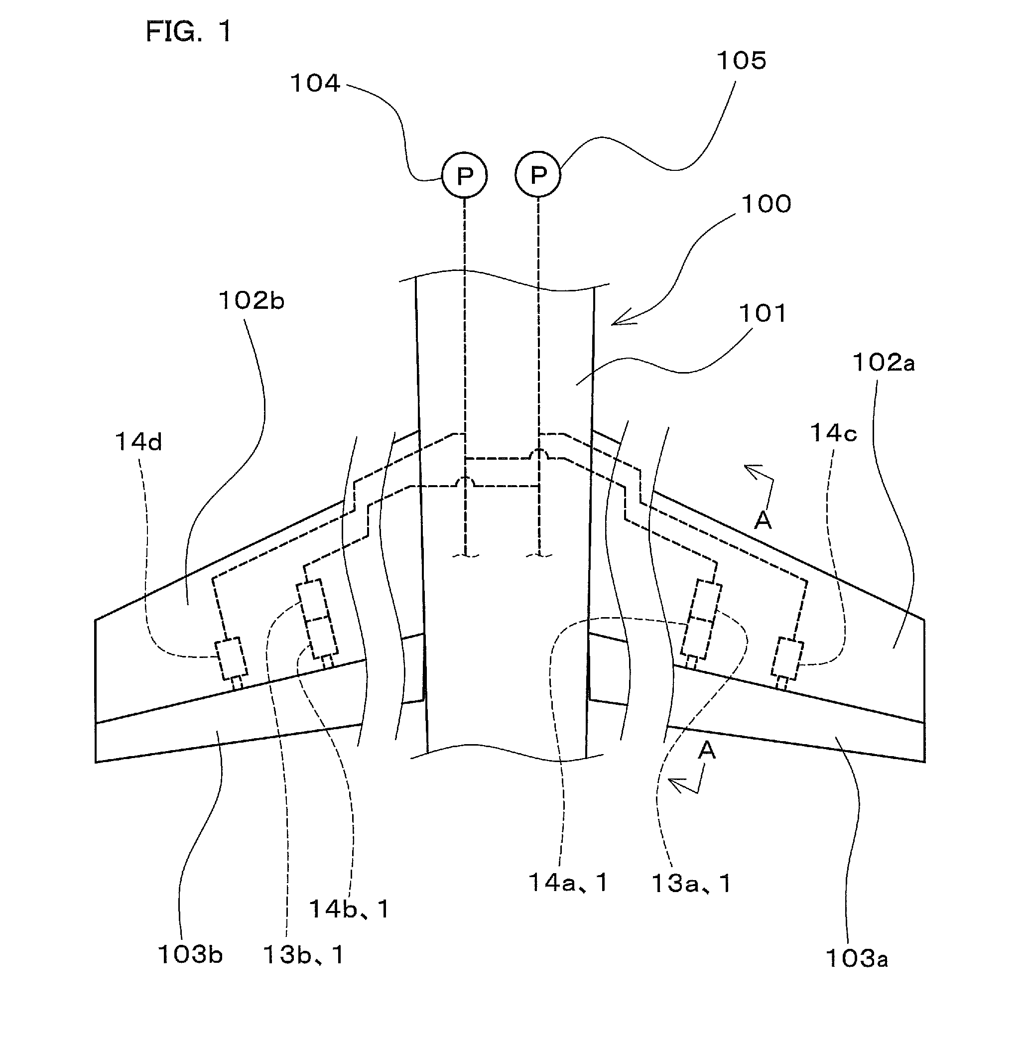
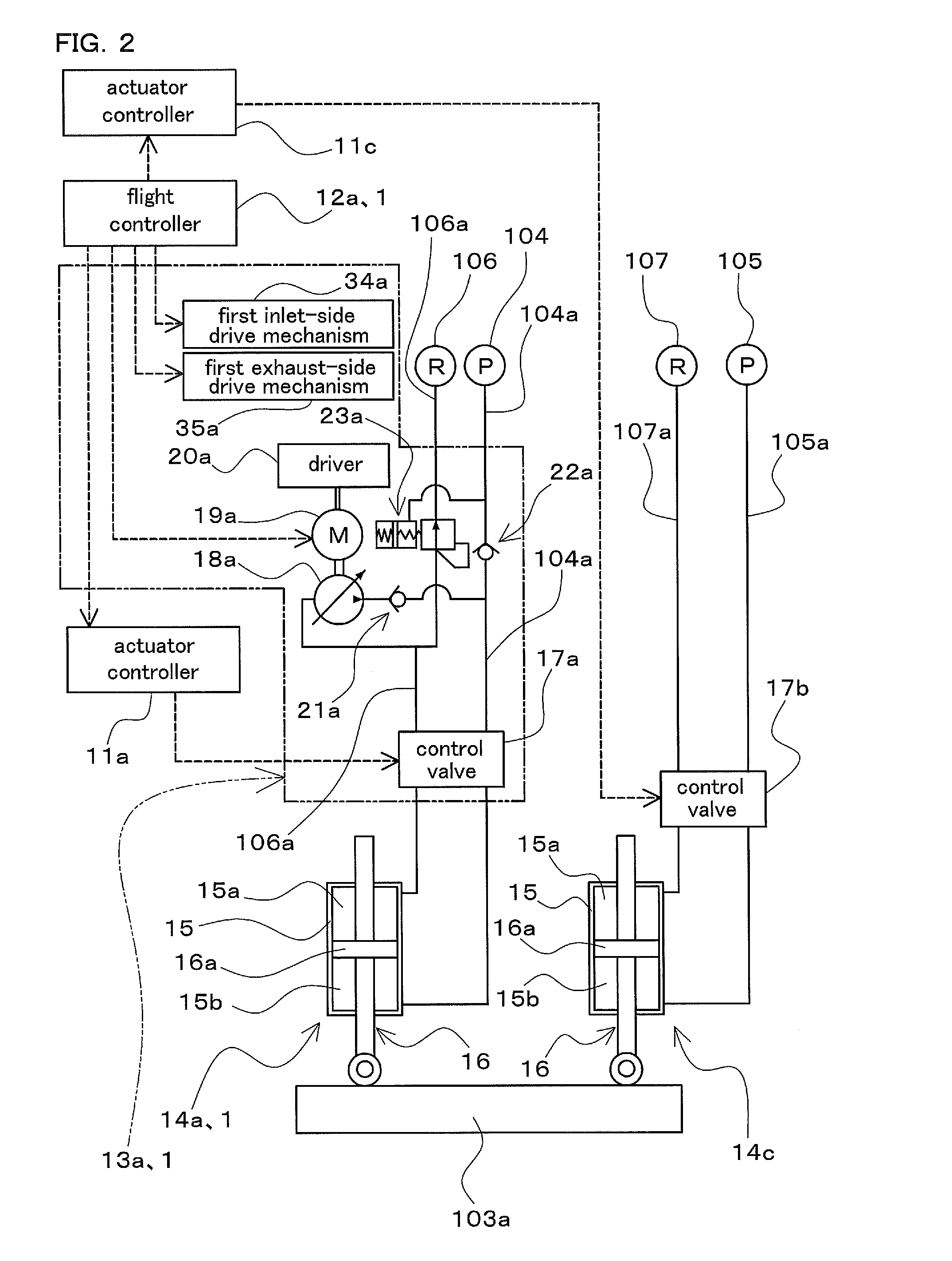
[0029]FIG. 1 is a diagram schematically showing part of an aircraft 100 to which a hydraulic system 1 for aircraft actuators (hereinafter, also simply referred to as a “hydraulic system 1”) according to a first embodiment of the present invention is applied, showing part of a fuselage portion of a body 101 of the aircraft 100 and a pair of main wings (102a, 102b). In FIG. 1, the illustration of the intermediate portions of the main wings (102a, 102b) is omitted.

[0030]The main wing 102a is provided with an aileron 103a as a moving surface (flight control surface) constituting a control surface of the aircraft 100. Likewise, the main wing 102b is provided with an aileron 103b as a moving surface (flight control surface) constituting a control surface of the aircraft 100. As illustrated in FIG. 1, the aileron 103a of the main wing 102a is configured to be driven by a plurality of (for example, two) actuators (14a, 14c). The aileron 103b of the main wing 102b is also configured to be dr...

second embodiment

[0107]Next, a hydraulic system 2 (hereinafter, also simply referred to as a “hydraulic system 2”) for aircraft actuators and a hydraulic system 3 for aircraft actuators (hereinafter, also simply referred to as a “hydraulic system 3”) according to a second embodiment of the present invention will be described. FIGS. 7 and 8 are schematic diagrams showing part of an aircraft 100 to which the hydraulic system 2 and the hydraulic system 3 are applied, showing a rear part of a body 101 of the aircraft 100, a pair of tailplanes (109a, 109b), and a vertical tail 111. Note that the vertical tail 111 is schematically shown as being separated from the body 101.

[0108]The hydraulic system 2 shown in FIG. 7 includes a first actuator 14a and a second actuator 14b, hydraulic apparatuses (13a, 13b), and flight controllers (12a, 12b) (not shown), as with the hydraulic system 1 of the first embodiment. However, the configuration of the hydraulic system 2 is different from that of the hydraulic system...


PUM


Abstract

When a loss or degradation in the function of one of a first aircraft central hydraulic power source and a second aircraft central hydraulic power source occurs, a controller performs a control so as to operate the other backup hydraulic pump, out of a first backup hydraulic pump and a second backup hydraulic pump, which is connected downstream of the other hydraulic power source, which is the other of the first and second aircraft central hydraulic power sources. Oil flowing through the other backup hydraulic pump is cooled by an oil cooler of the other hydraulic power source by operation of the other backup hydraulic pump in a state where the other hydraulic power source is being operated.

Description

CROSS-REFERENCE TO RELATED APPLICATIONS[0001]This application claims priority to Japanese Patent Application No. 2010-148545. The entire disclosure of Japanese Patent Application No. 2010-148545 is hereby incorporated herein by reference.BACKGROUND OF THE INVENTION[0002]1. Field of the Invention[0003]The present invention relates to an aircraft actuator hydraulic system that includes hydraulically operated actuators for driving a control surface of an aircraft and that supplies pressure oil to the actuators.[0004]2. Description of Related Art[0005]An aircraft is provided with control surfaces that are formed as moving surfaces (flight control surfaces) and are configured as an aileron, an elevator, a rudder and the like. A hydraulically operated actuator is often used as an actuator for driving such control surfaces. Further, pressure oil is supplied to such an actuator from an aircraft central hydraulic power source. However, a loss or degradation in the function (pressure oil supp...

Claims


Application Information

Patent Timeline
Patent Type & Authority Patents(United States)
IPC IPC(8): B64C5/10
CPCB64C13/42F15B18/00Y02T50/44F15B2211/62F15B2211/8752F15B2211/20576Y02T50/40
Inventor FUKUI, ATSUSHI
Owner NABLESCO CORP
Why Eureka
Try Eureka