Systems and methods for producing thermal mechanical fatigue on gas turbine rotors in a spin test environment

a technology of thermal mechanical fatigue and gas turbine rotor, which is applied in the direction of instruments, heat measurement, structural/machine measurement, etc., can solve the problems of inconsistent rotation component life, /inelastic strain and material behavior, and different operators may experience inconsistent rotating component life, etc., to reduce the risk of thermal radiation stray, improve heating efficiency, and reduce the effect of thermal radiation

Inactive Publication Date: 2013-04-16
SCHENCK USA CORP
View PDF9 Cites 3 Cited by
  • Summary
  • Abstract
  • Description
  • Claims
  • Application Information

AI Technical Summary

Benefits of technology

[0013]According to an exemplary embodiment, the high-heat flux source is a quartz lamp closely coupled to the test component. The quartz lamp can provide localized high-heat flux, such as to a rim area of the test component. The quartz lamp can be controlled to apply a high-heat flux to the rim area of the test component or in relatively tight annuli to produce a thermal gradient in a radial direction of the rotating test component. Power to the quartz lamp can be modulated to produce the desired high heat flux to be applied to the test component. The use of the quartz lamp permits the creation of a controllable gradient on the test component that can be imposed and removed as desired to provide a flexible and simplified test environment for applying arbitrary thermal and mechanical loads to a test component.
[0016]The control system can be used to set a profile for thermal and mechanical loading on the test component, as well as to control for limits on parameters, for reasons such as safety or component integrity. Controls can be provided to permit set point or other control parameters to be changed or updated during a test to permit real time changes or control, i.e., “on the fly.” The control system permits implementation of control strategies, including thermal control strategies, to contribute to minimizing cycle time, including thermal cycle time, to reduce testing duration and cost.
[0021]According to an embodiment, a desired radial thermal gradient is achieved by focusing thermal energy to limit stray thermal radiation. The thermal gradient may be generated by directing a high heat flux source to specific locations on the object under test. The high heat flux source may produce high heat through induction, laser, quartz lamps, focused quartz lamps, impingement, resistive or other sources capable of generating high heat flux. Advantageously, the test facility may include heat rejection devices or employ heat rejection methods to improve heating efficiency.

Problems solved by technology

The phase problem is also affected by operability since power manipulation, to a certain extent, determines the severity of the gradient.
This creates a situation where different operators may experience inconsistent rotating component life strictly based on how they operate their engines.
Structural integrity personnel have the challenge of trying to establish a life limit for components with simultaneously changing elastic / inelastic strains and material behavior.
Data derived from material coupon testing is of limited value because there is no current material testing method (outside of an actual jet engine) that induces a radial thermal gradient in synchronization with realistic in-service rotational speeds.
In other words, there is no method that simulates a thermal and mechanical fatigue (TMF) load cycle.
Given the extensive testing used to generate durability and life prediction models, and the cost of full-up engine tests ($6M+each), no cost-effective way to conduct representative TMF testing is presently available.
Current component design methods are also very costly, often requiring several iterations to achieve a “best effort” solution, resulting in increases of many millions of dollars and months of schedule to an engine program.
Additionally, TMF related failures in engine hot sections are a critical factor driving class A mishaps, and low Total Accumulated Cycles (TAC) useful life, Mean Time Between Failure (MTBF), and Mean Time Between Maintenance (MTBM).
Analytical based life prediction systems have fallen short in assessing component life with the result of imposing financial burdens on operators for replacement parts.
While analysis tools exist that can model engine components and TMF loading, the results of such model analyses may not adequately predict the response of objects and materials subjected to the environment typically encountered in the gas turbine engine.
For example, estimates or assumptions made in constructing such a model may have an exaggerated or underrepresented impact on the test results.
Correlation between physical test results and predicted results can sometimes vary widely, often leading designers to specify conservative estimates for predicted lifetimes of engine components.
For example, engineering conservatism due to lack of knowledge regarding material behavior under severe TMF conditions typically results in shorter prescribed lives for hot section rotational components.
To date, spin pit based TMF testing has been somewhat impractical due to the lack of high heat flux ovens capable of duplicating engine thermal excursions.

Method used


Image

  • Systems and methods for producing thermal mechanical fatigue on gas turbine rotors in a spin test environment
  • Systems and methods for producing thermal mechanical fatigue on gas turbine rotors in a spin test environment
  • Systems and methods for producing thermal mechanical fatigue on gas turbine rotors in a spin test environment

Examples


Embodiment Construction

[0046]The entire disclosure of U.S. Provisional Application No. 61 / 132,686, filed Jun. 20, 2008 is hereby incorporated herein by reference.

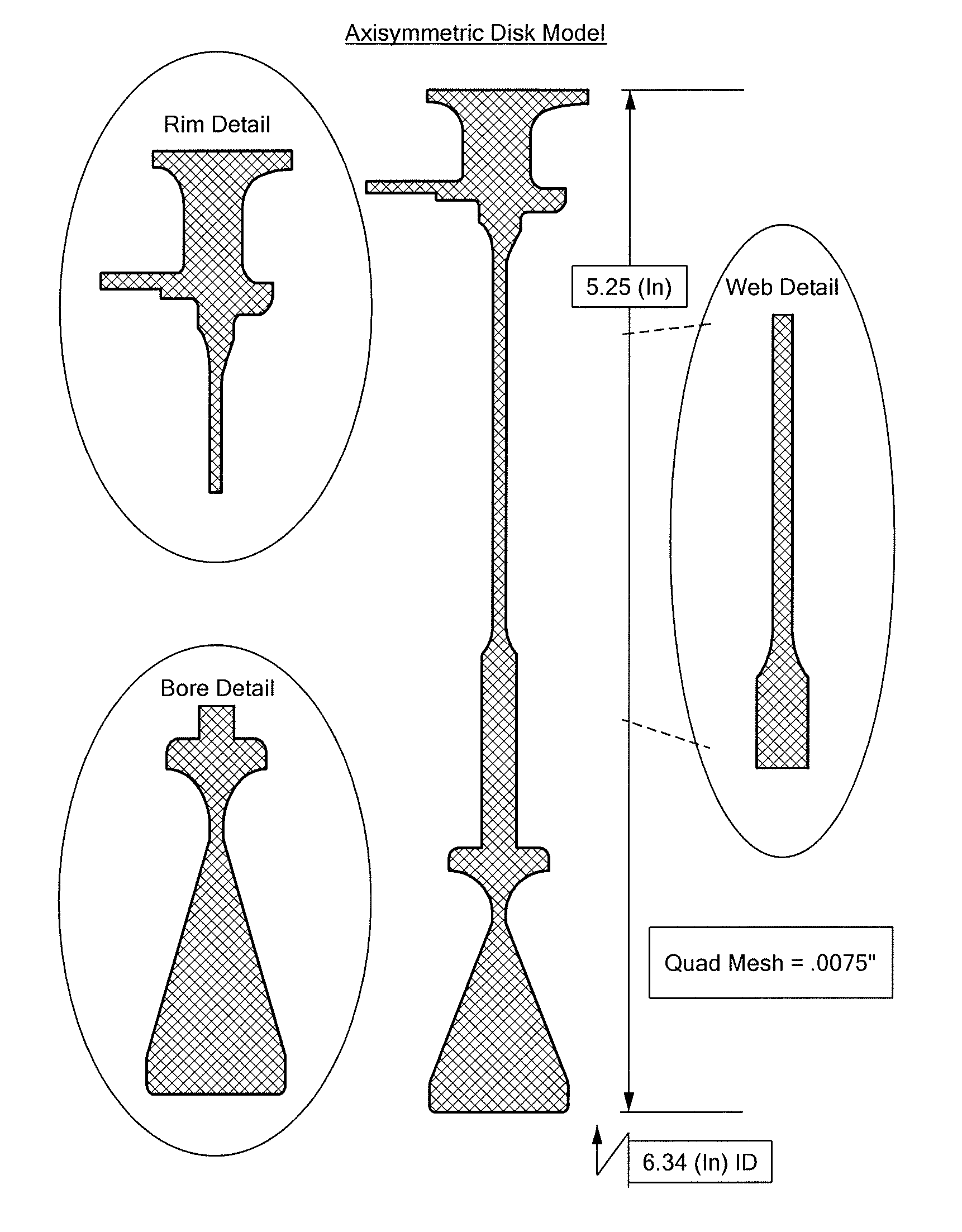
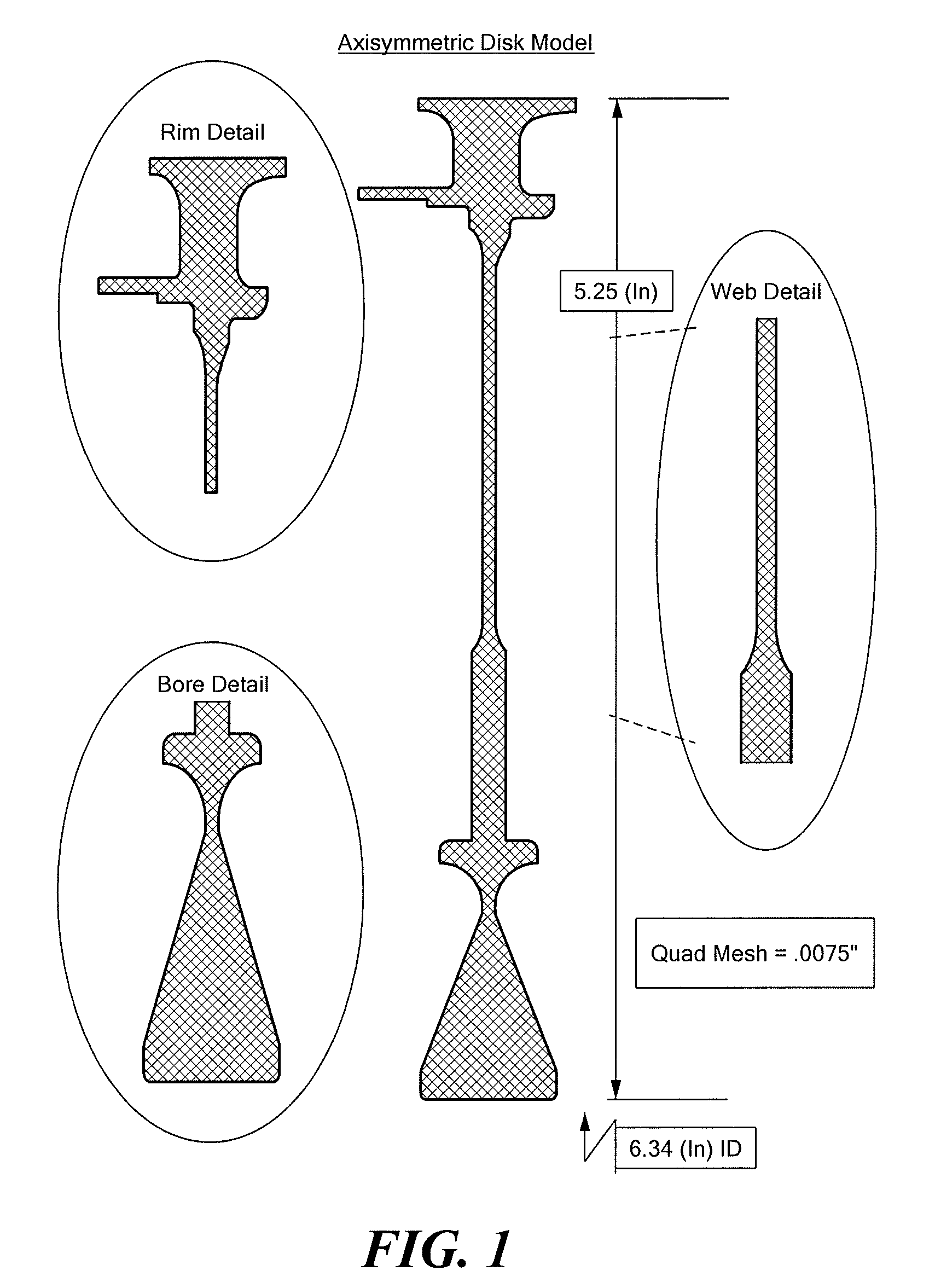
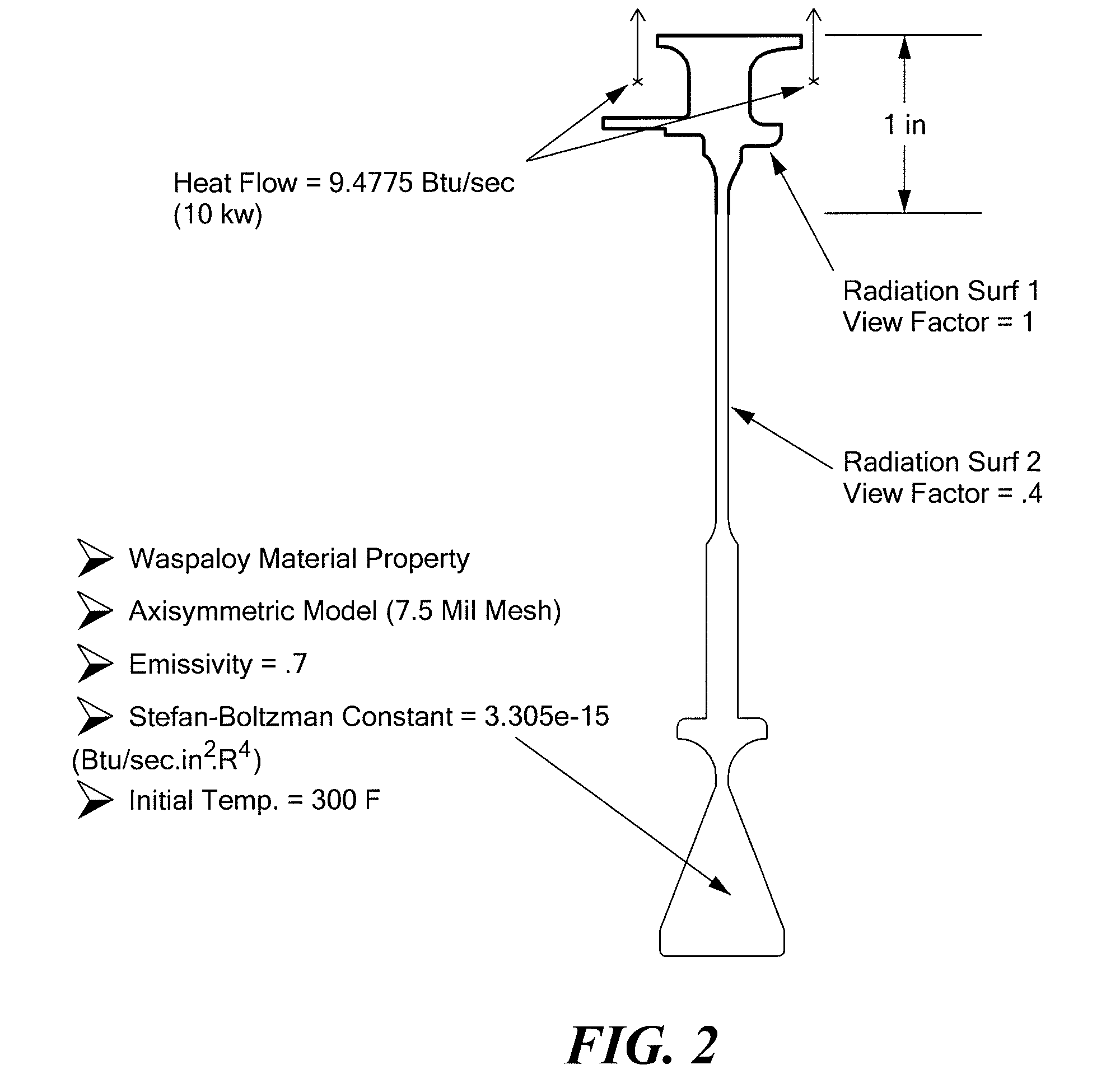
[0047]It is generally accepted that there is the potential for determining significant additional safe operating life in gas turbine engine components. Extending the useful service life for such engine components represents a considerable savings to the Department of Defense (DoD) and commercial aero turbine and industrial gas turbine operators. Correlation of FEA models with empirical thermal gradient testing can help reduce the risk of deviating from current conservative life estimates and potentially lead to certification of engine components at a greater number of cycles or Total Accumulated Cycles (TAC's) before they are retired. Such certification may save commercial and institutional operators, including military or other governmental operators, significant costs by increasing the time between inspections and reducing the amount of spare p...


PUM

PropertyMeasurementUnit
operating temperaturesaaaaaaaaaa
temperaturesaaaaaaaaaa

Abstract

A test facility includes a heat source to thermally load a test object being mechanically loaded by rotation imposed by a spin test rig. The heat source can be a quartz lamp controlled to provide a thermal load with a differing phase than the mechanical load. Testing cycles can be run for the test object, with impingement cooling permitting the removal of the thermal load between cycles. The test facility emulates operating conditions in a gas turbine engine to impose realistic thermal and mechanical fatigue stress on the test component.

Description

CROSS-REFERENCE TO RELATED APPLICATIONS[0001]This application claims the benefit of U.S. Provisional Application No. 61 / 132,686, filed Jun. 20, 2008, the entire disclosure of which is hereby incorporated herein by reference.STATEMENT REGARDING FEDERALLY SPONSORED RESEARCH OR DEVELOPMENT[0002]This invention was made with government support under Contact No. FA8650-05-C-2528 awarded by the United States Air Force. The government has certain rights in the invention.BACKGROUND OF THE INVENTION[0003]The modern gas turbine engine flow path undergoes a dramatic series of axial temperature changes from fan inlet to low turbine discharge. Because the flow path is a near closed system, isolated from the components inboard and outboard, the blades, vanes, and disk rims contained within the system reach operating temperatures up to 2500° F. (surface temp.) in the gas path, and 2500-3200° F. rim temperatures in the high turbine. Conversely, the disk webs and bores which are inboard of the flow p...

Claims


Application Information

Patent Timeline
Patent Type & Authority Patents(United States)
IPC IPC(8): G01N3/00G01K1/00G01K3/00
CPCG01N3/18G01N3/32G01N3/60G01M13/00G01N2203/0071G01N2203/0222G01M99/002
Inventor WAWRZONEK, PAULSONNICHSEN, H. ERICMURNER, ROBERT L.
Owner SCHENCK USA CORP
Why Eureka
Try Eureka