Steering apparatus for outboard motor

a technology of steering apparatus and outboard motor, which is applied in the direction of steering initiation, special purpose vessels, vessel construction, etc., can solve the problems of large operating force, damage to protective boots, and outboard motors that are likely to interfere with drive system components, so as to prevent damage to protective boots

Active Publication Date: 2013-04-16
NHK MEC CORP
View PDF17 Cites 5 Cited by
  • Summary
  • Abstract
  • Description
  • Claims
  • Application Information

AI Technical Summary

Benefits of technology

[0009]Accordingly, the object of this invention is to provide a steering apparatus for an outboard motor configured so that an electric actuator unit can be formed in a compact manner and damage to protective boots can be prevented.
[0014]According to the present invention, the feed screw can be rotated in such a manner that torques are applied to the feed screw through its opposite ends by means of the pair of electric motors. Therefore, the outside diameter of the feed screw can be reduced compared with the case of a conventional actuator unit in which a feed screw is rotated by a single motor. In addition, the feed screw and protective boots are concentrically arranged inside the cover member, and the electric motors are disposed individually at the opposite ends of the feed screw. Thus, the radial dimension of the electric actuator can be made compact. Since the protective boots are protected by the cover member, moreover, the protective boots can be prevented from being damaged by contacting the members around the actuator unit.

Problems solved by technology

Since these steering apparatuses are operated manually (or by an operator's power), they require a considerably large operating force, depending on the boat operating conditions, and hence, leave room for improvement.
The steering apparatus of this type has a problem that various cables, fuel supply pipe, etc., attached to the outboard motor are likely to interfere with the drive system components.
In some cases, the protective boots may be damaged and leave the rack and pinion to be eroded by seawater or the like.
As the drive system components pivot downwardly when the outboard motor is tilted up, moreover, the greatly projecting drive system components are likely to interfere with members on the boat body, thus leaving room for improvement.

Method used


Image

  • Steering apparatus for outboard motor
  • Steering apparatus for outboard motor
  • Steering apparatus for outboard motor

Examples


first embodiment

[0038]A boat comprising a steering apparatus according to the present invention will now be described with reference to FIGS. 1 to 12.

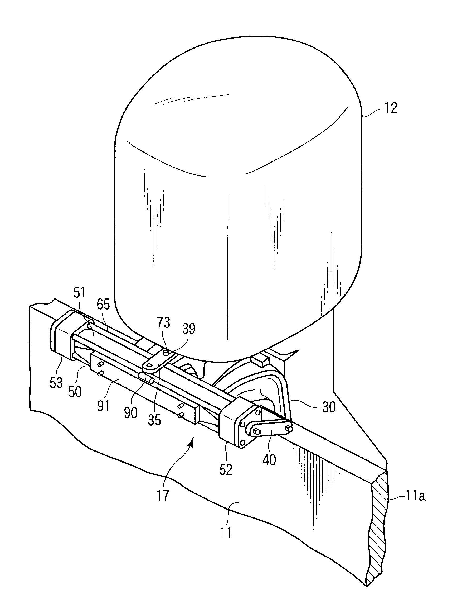
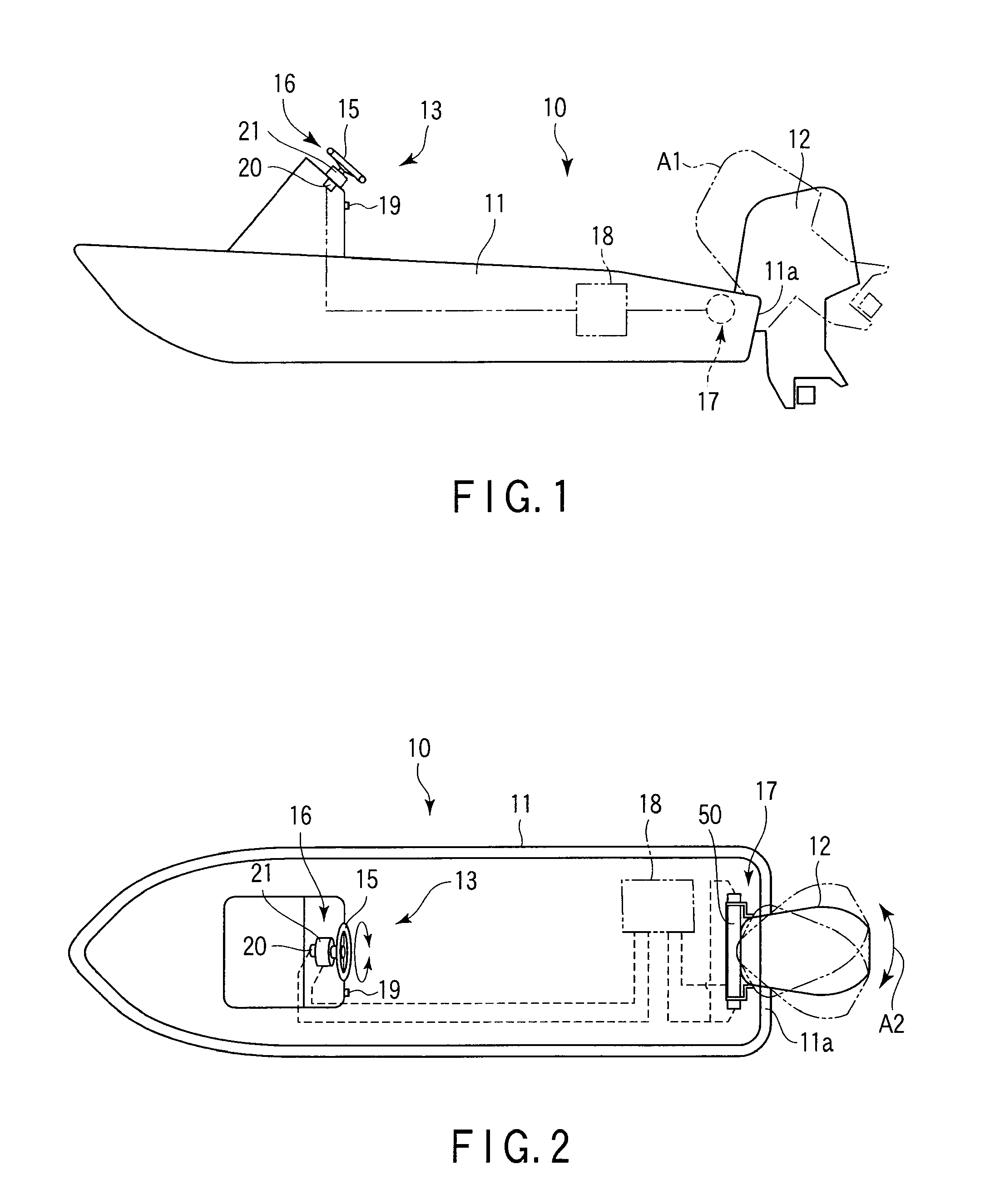
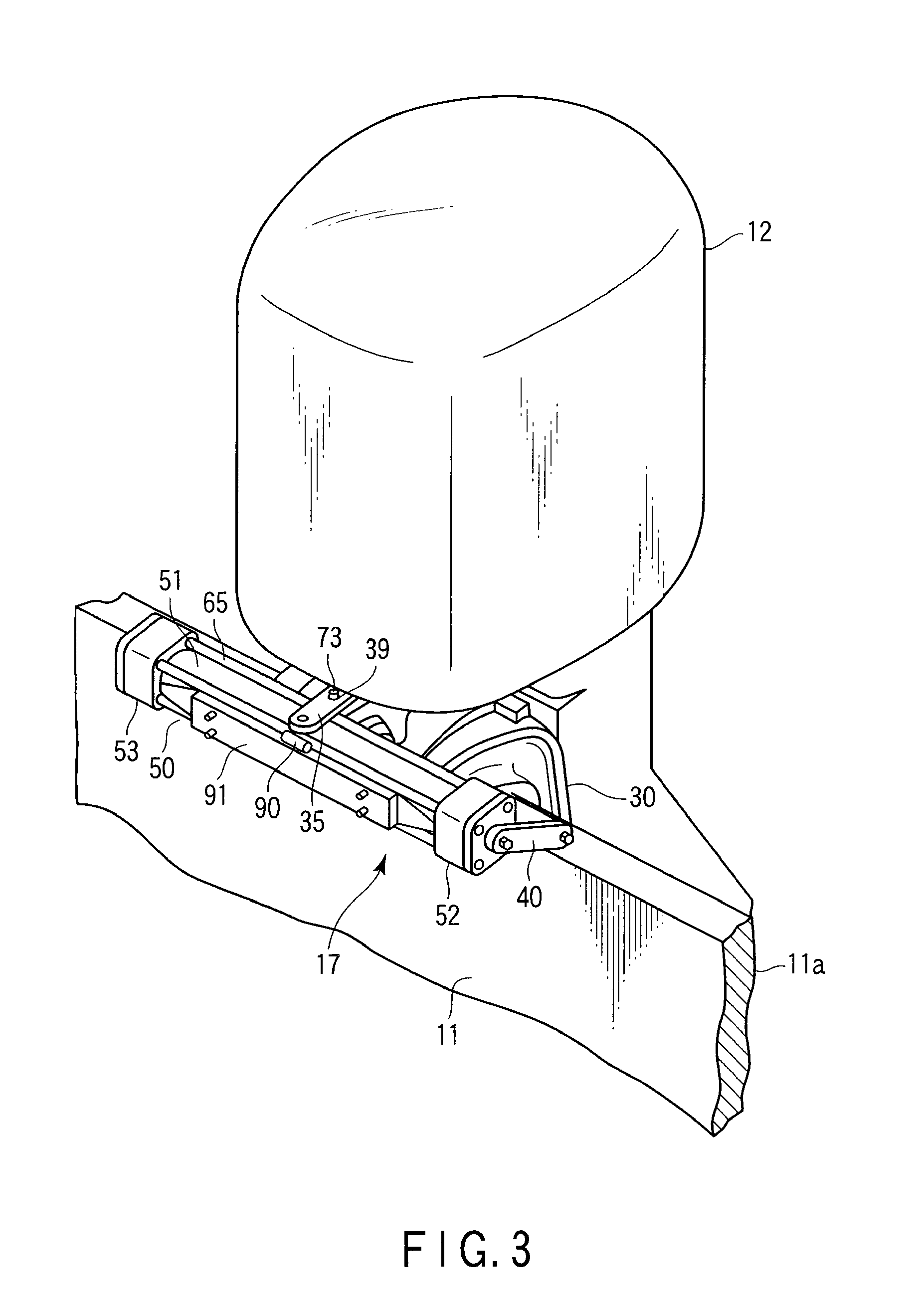
[0039]FIGS. 1 and 2 show an example of a boat 10. The boat 10 comprises a boat body 11, outboard motor 12, and steering apparatus 13. The outboard motor 12 can be tilted up, as indicated by two-dot chain line A1 in FIG. 1. Further, the outboard motor 12 can turn to starboard and port, as indicated by arrow A2 in FIG. 2. The steering apparatus 13 comprises a helm device 16 comprising a helm 15, electric actuator unit 17 disposed at the rear part of the boat body 11, control unit 18, etc. The actuator unit 17 functions as a drive source for changing the steering angle of the outboard motor 12. The control unit 18 electrically controls the actuator unit 17. This control unit 18 is configured to be turned on and off by a power switch 19.

[0040]The helm device 16 comprises a helm sensor 20, friction mechanism 21, etc. An example of the helm sensor 20 compri...


PUM


Abstract

Support arms are disposed on a tilting shaft on a bracket of an outboard motor. An electric actuator is mounted between the support arms. The electric actuator includes a cover member, first and second electric motors disposed individually on the opposite ends of the cover member, a feed screw configured to be rotated by the electric motors, a nut member configured to move along an axis as the feed screw rotates, a drive arm configured to move integrally with the nut member and transversely relative to the boat body, and protective boots. The drive arm is connected to a steering arm through an engaging member. If the drive arm moves in the direction of the axis along the cover member, the steering angle of the steering arm changes depending on the degree of movement of the drive arm.

Description

CROSS-REFERENCE TO RELATED APPLICATIONS[0001]This application is a Continuation Application of PCT Application No. PCT / JP2011 / 060535, filed May 2, 2011 and based upon and claiming the benefit of priority from prior Japanese Patent Application No. 2010-181353, filed Aug. 13, 2010, the entire contents of all of which are incorporated herein by reference.BACKGROUND OF THE INVENTION[0002]1. Field of the Invention[0003]This invention relates to a steering apparatus for an outboard motor comprising an electric actuator unit.[0004]2. Description of the Related Art[0005]Conventionally, there has been known a steering apparatus for an outboard motor in which a hydraulic pump is provided on, for example, a helm (steering wheel), and a hydraulic actuator configured to be driven by the hydraulic pump is disposed near the outboard motor. In this steering apparatus, an oil pressure produced by the hydraulic pump serves to redirect the outboard motor. Also known is a mechanical steering apparatus ...

Claims


Application Information

Patent Timeline
Patent Type & Authority Patents(United States)
IPC IPC(8): B63H20/08B63H25/10
CPCB63H20/08B63H25/02
Inventor OOSHITA, SACHIOMAKITA, YOSHIHIRO
Owner NHK MEC CORP
Why Eureka
Try Eureka