LED light bulb

a technology of led light bulb and led arc, which is applied in the direction of discharge tube main electrodes, semiconductor devices for light sources, lighting and heating apparatus, etc., can solve the problems of reducing the working time of leds, causing damage to leds or driving circuits, and constantly generating waste heat, etc., to reduce the heat conduction effect, reduce the working time, and prevent deformation

Inactive Publication Date: 2013-04-16
CHUANG SHENG YI
View PDF20 Cites 95 Cited by
  • Summary
  • Abstract
  • Description
  • Claims
  • Application Information

AI Technical Summary

Benefits of technology

[0008]In view of the conventional LED light bulb using screws to fasten the LED baseboard by a simple technique but increasing working time and causing deformation of the LED baseboard due to temperature rising to decrease heat conduction effect between the LED baseboard and heat sink and result in a vicious cycle of poor cooling, the present invention aims to provide an LED light bulb that includes a light transparent shell, a power receiving base, a heat sink and a coupling holder located between the light transparent shell and power receiving base, at least one light source baseboard located in the light transparent shell, and a power conversion board electrically connected to the light source baseboard and power receiving base. The heat sink has a housing chamber to hold the power conversion board and also an annular coupling wall to couple with the light source baseboard. The light source baseboard has a contact surface on the circumference corresponding and fastening to the coupling wall to form compact coupling so that the light source baseboard is held tightly on the heat sink to prevent deformation caused by temperature. The compact coupling between the light source baseboard and heat sink also provides improved heat conduction effect.

Problems solved by technology

However, since driving the LEDs requires a steady DC current, waste heat will be constantly generated and accumulated when the driving circuit converts AC power into DC power.
Moreover, the DC power passing through the impedance of LEDs also generates a lot of waste heat.
All these result in overhigh temperature after long-term use that could damage the LEDs or driving circuit, or shorten the lifespan thereof.
However, the aforesaid techniques of fastening the LED baseboard via the screws have many disadvantages.
But such a structure also creates problems.
Hence a vicious cycle of poor cooling takes place.

Method used


Image

  • LED light bulb
  • LED light bulb
  • LED light bulb

Examples


Embodiment Construction

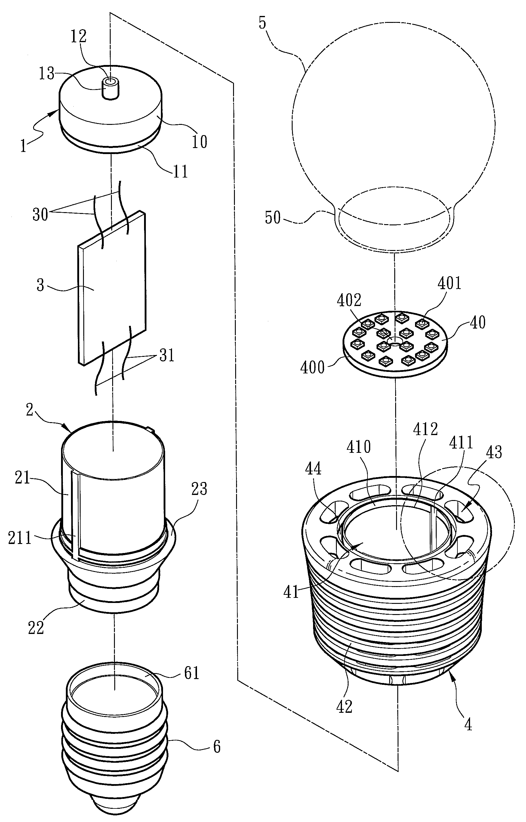
[0018]The present invention aims to provide an LED light bulb. Please refer to FIGS. 3A through 5 for a first embodiment of the invention. The LED light bulb includes a light transparent shell 5, a power receiving base 6, a heat sink 4 and a coupling holder 2 located between the light transparent shell 5 and power receiving base 6, at least one light source baseboard 40 located in the light transparent shell 5, and a power conversion board 3 electrically connected to the light source baseboard 40 and power receiving base 6. The power conversion board 3 is preferably a switch-type power circuit. The heat sink 4 has a housing chamber 41 to hold the power conversion board 3. The light source baseboard 40 holds a plurality of LEDs 401, and can be an aluminum baseboard containing a plurality of conductive wires. Based on present techniques, the aluminum baseboard can be formed by stacking a copper foil, conductive insulation material and an aluminum plate over one another. The copper foi...


PUM


Abstract

An LED light bulb includes a light transparent shell, a power receiving base, a heat sink and a coupling holder located between the light transparent shell and power receiving base, at least one light source baseboard held in the light transparent shell, and a power conversion board electrically connected to the light source baseboard and power receiving base. The heat sink has a housing chamber to hold the power conversion board and an annular coupling wall surrounded to form an area to couple with the light source baseboard. The light source baseboard has a contact surface on the circumference to form compact coupling with the coupling wall so that the light source baseboard is securely held on the heat sink without deforming at high temperature to provide improved heat conduction capability.

Description

[0001]This application is a continuation-in-part, and claims priority, of from U.S. patent application Ser. No. 13 / 012,581 filed on Jan. 24, 2011 now U.S. Pat. No. 8,258,683, entitled “INSULATION REINFORCING LIGHT BULB”, the entire contents of which are hereby incorporated by reference.FIELD OF THE INVENTION[0002]The present invention relates to an LED light bulb and particularly to a light bulb with an LED baseboard and a heat sink coupled tightly.BACKGROUND OF THE INVENTION[0003]Light emitting diode (LED) provides many advantages such as longer lifespan, less power consumption, higher illumination and more eco-friendly materials. With advance of LED fabrication process and lower cost thereof, LED is not only adopted on traffic lights or indication lights of electric appliances, it also can be used on environmental decoration or lighting fixtures. In order to allow the LED to adapt to the general light bulb, some techniques have been proposed in prior art. For instance, R.O.C. pate...

Claims


Application Information

Patent Timeline
Patent Type & Authority Patents(United States)
IPC IPC(8): F21V29/00H01J7/24
CPCF21K9/135F21Y2101/02F21Y2105/001F21Y2105/10F21K9/232F21Y2115/10
Inventor CHUANG, SHENG-YI
Owner CHUANG SHENG YI
Why Eureka
Try Eureka