Upconverter

a wireless magnetic resonance imaging and upconverter technology, applied in the direction of variable-capacitor element amplifiers, instruments, and reradiation, can solve the problems of increasing the down-time between scans, adding cost and inconvenience to the structure, and reducing the desired performance, so as to achieve low-noise amplifier output

Active Publication Date: 2013-04-16
SIEMENS HEALTHCARE GMBH
View PDF30 Cites 7 Cited by
  • Summary
  • Abstract
  • Description
  • Claims
  • Application Information

AI Technical Summary

Benefits of technology

[0009]The present invention provides diversity with more than one path from a local coil to more than one corresponding microwave antenna, so increasing the number of paths from the microwave antenna on the patient to the bore antennas.

Problems solved by technology

These add cost and inconvenience to the structure.
In use, the requirement to connect the cables and sterilize them between scanning one patient and the next leads to increased down-time between scans.
However, in an MRI scanner with wireless coils, using a two port upconverter core, there are two mechanisms which cause a reduction in desired performance.
The first is the local oscillator illumination at the patient microwave antenna not being adequate for powering the upconverter core; and the second is that the view of the patient antenna by the bore antenna connected to the receiver is not good enough (e.g. the bore antenna out of range, obscured, or not in the main beam), even if the local oscillator (LO) illumination provides adequate power for the upconverter core.

Method used


Image

  • Upconverter
  • Upconverter
  • Upconverter

Examples


Embodiment Construction

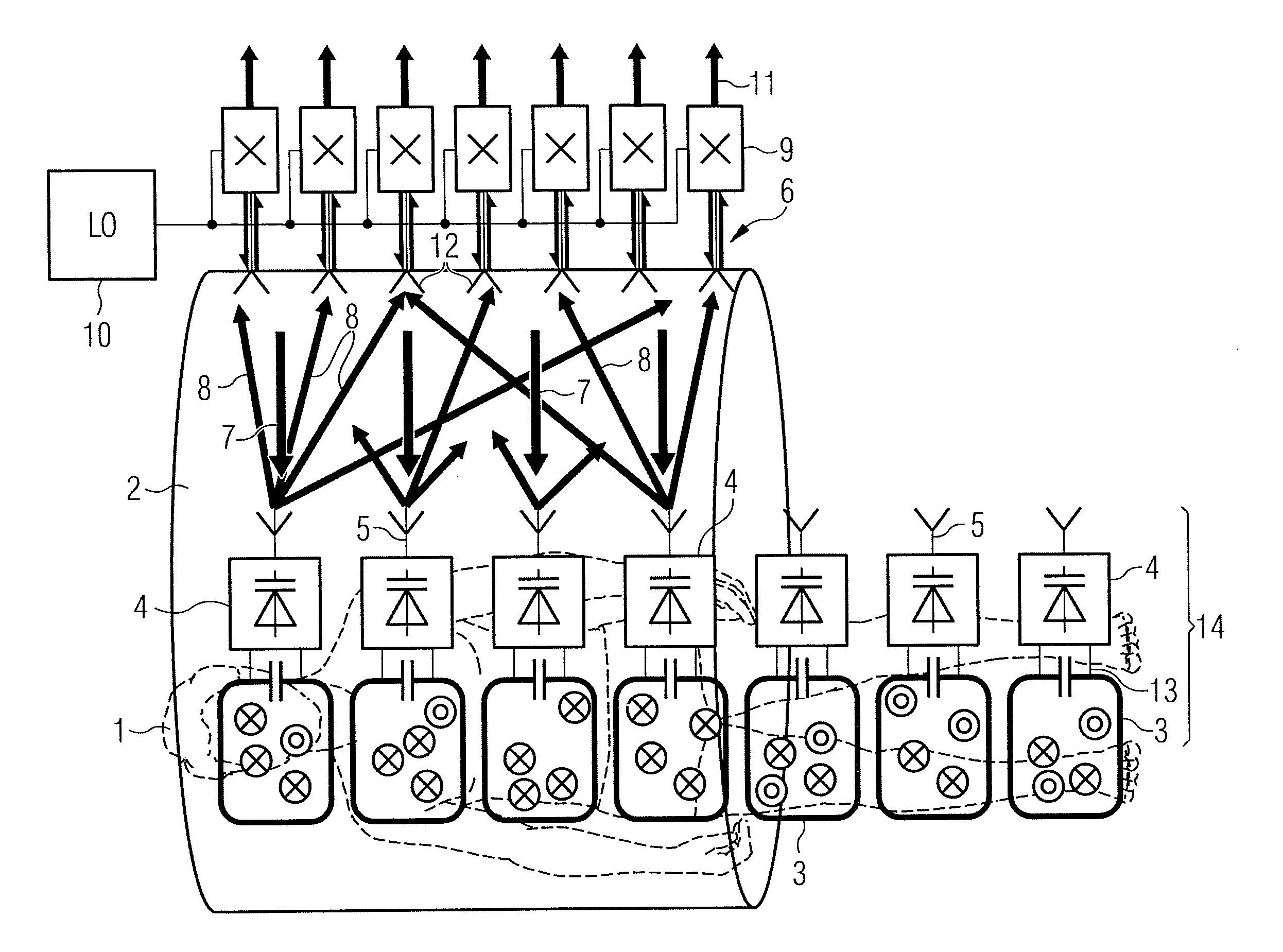
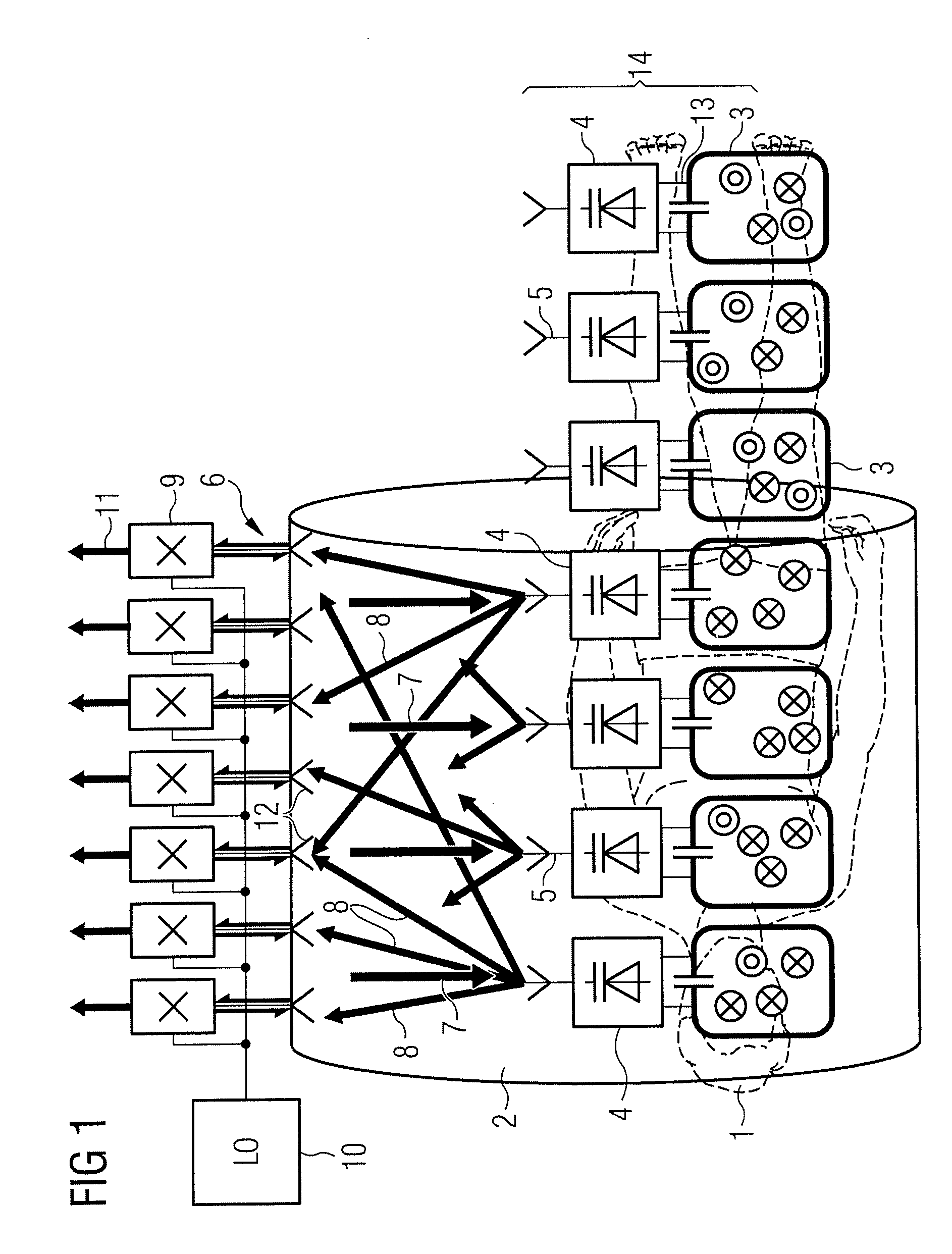
[0034]An example of an MRI system using a MIMO microwave link is shown in FIG. 1. However, other architectures are possible and the invention is not limited to the one described below. FIG. 1 shows a patient 1 within an MRI scanner bore tube 2. A mat covers the part of the patient to be scanned and embedded in the mat are a plurality of local coils 3. Associated with each local coil 3 is an upconverter 4 and microwave antenna 5. Transceivers 9 connected to an array 6 of antennas 12 are integrated into the scanner bore 2. The frequency upconverter 4 for each patient mat coil 3 produces signals for transmission to the array of transceivers in the scanner bore 2. A signal generator 10 generates a local oscillator (LO) signal at 2.44 GHz, or other chosen microwave frequency, which feeds the transceivers connected to the antenna array 6 to illuminate the patient coil electronics 14 with a signal 7 at the local oscillator frequency.

[0035]The same LO signal in the transceivers converts the...


PUM


Abstract

A magnetic resonance imaging system upconverter stage has a number of local coils and a number of upconverters to receive a signal from an output of each coil. Each upconverter has a number of two port upconverter cores, each core having a first port to receive a signal from a local coil and a second port to output an upconverted signal at upper and lower sideband frequencies through an antenna coupled to the second port. The inputs of the plurality of upconverter cores are connected in parallel, and at least one antenna is associated with the second port of each core.

Description

BACKGROUND OF THE INVENTION[0001]1. Field of the Invention[0002]The present invention relates to an upconverter for a wireless magnetic resonance imaging (MRI) scanner, in particular where the orientation of the local coil antenna is unpredictable, or its position cannot be guaranteed to be suitable for reception or transmission.[0003]2. Description of the Prior Art and Related Subject Matter[0004]MRI scanners use a combination of a strong constant magnetic field (B0) from a superconducting magnet which is modified by gradient fields generated by gradient coils, together with a rotating magnetic field (B1) from a radio frequency (RF) antenna to excite nuclear magnetic resonances in the body that generate short term RF signals that are received to build up a tomographic image.[0005]All current-generation MRI scanners employ arrays of local coils mounted in close proximity to the scanned patient to receive the RF with maximum possible signal to noise ratio (SNR). The local coils that ...

Claims


Application Information

Patent Timeline
Patent Type & Authority Patents(United States)
IPC IPC(8): G01V3/00G01R33/20
CPCG01R33/3415G01R33/3692H03F7/04G01R33/3607
Inventor CORK, PETERHULBERT, ANTHONY PETER
Owner SIEMENS HEALTHCARE GMBH
Why Eureka
Try Eureka