Check patentability & draft patents in minutes with Patsnap Eureka AI!

Clock frequency divider circuit, clock distribution circuit, clock frequency division method, and clock distribution method

a clock distribution circuit and clock frequency divider technology, applied in the direction of generating/distributing signals, pulse techniques, oscillators, etc., can solve the problem of deteriorating performance, so-called clock skew, and the related-art technique does not consider the communication with the communication circuit n, so as to reduce the power consumption of the clock tree circuit

Active Publication Date: 2013-04-16
NEC CORP
View PDF13 Cites 11 Cited by
  • Summary
  • Abstract
  • Description
  • Claims
  • Application Information

AI Technical Summary

Benefits of technology

The present invention provides a clock frequency divider circuit that allows proper communication with circuits that operate using different clock frequencies. It also reduces power consumption for clock tree circuits. Also, a clock distribution circuit and method are provided for proper distribution of clock signals.

Problems solved by technology

Further, as semiconductor devices become increasingly larger in scale and their operating frequencies become increasingly faster, the relative phase deviation between clock signals distributed in the semiconductor device, i.e., the so-called “clock skew” has been becoming a serious problem.
If the clock skew becomes larger, the upper limit of the operating frequency of synchronous circuits is restricted, thus causing deterioration in performance.
However, this related-art technique does not give any consideration to the communication with the communication circuit N operating by a clock having a different frequency.
Therefore, there is a problem that the communication with the communication circuit N requires a special clock transfer circuit and / or special timing design.
In addition, there is another problem that the communication performance deteriorates because of the above-described problem.
Further, there is another problem that when the frequency division ratio is changed, it is necessary to change the communication timing with the communication circuit N according to that change.
However, the clock frequency divider circuit 100 in the related art does not give any consideration to the communication with a circuit operating by a clock having a different frequency.
Therefore, in the clock frequency divider circuit in the related art, there is a problem that the communication with a circuit operating by a clock having a different frequency requires a special clock transfer circuit and / or special timing design to realize an expected proper communication operation.
As a result, there is another problem that the communication performance deteriorates.
Further, there is another problem that when the frequency division ratio is changed, it is necessary to change the timing of communication with the circuit operating by a clock having a different frequency according to that change.
Therefore, there is another problem that the power consumption of the clock tree circuit 20 is large.

Method used


Image

  • Clock frequency divider circuit, clock distribution circuit, clock frequency division method, and clock distribution method
  • Clock frequency divider circuit, clock distribution circuit, clock frequency division method, and clock distribution method
  • Clock frequency divider circuit, clock distribution circuit, clock frequency division method, and clock distribution method

Examples


first exemplary embodiment

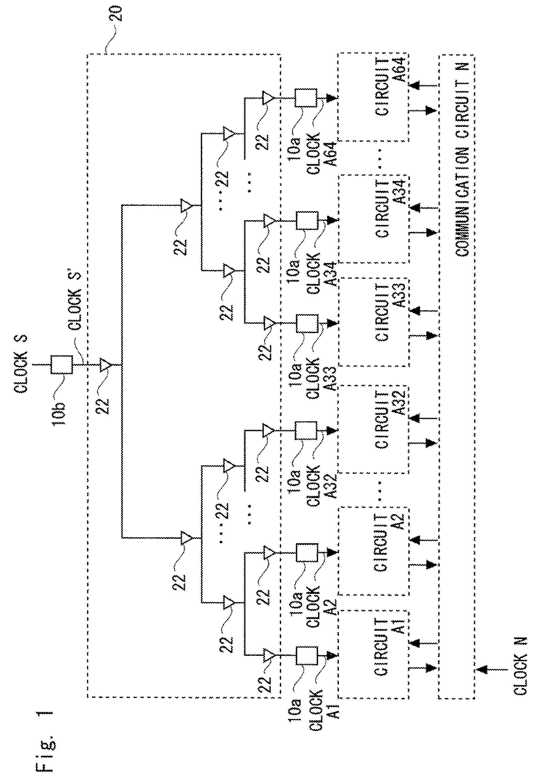
[0042]Firstly, a clock distribution circuit in accordance with a first exemplary embodiment of the present invention is explained with reference to FIG. 1. FIG. 1 shows an example of a semiconductor integrated circuit including circuits Ai (i is integer and 1≦i≦64) operating by clocks Ai (i is integer and 1≦i≦64), a communication circuit N operating by a clock N, a clock tree circuit 20, and clock frequency divider circuits 10a and 10b. The same components as those of the semiconductor integrated circuit in the related art shown in FIG. 8 are denoted by the same signs.

[0043]The circuits Ai are connected to the communication circuit N, and communicate with each other through the communication circuit N. Each of the clock frequency divider circuits 10a is connected to one of the output ends of the clock tree circuit 20 and the clock frequency divider circuit 10b is connected to the input end of the clock tree circuit 20, thus forming a clock distribution circuit.

[0044]The clock tree c...

second exemplary embodiment

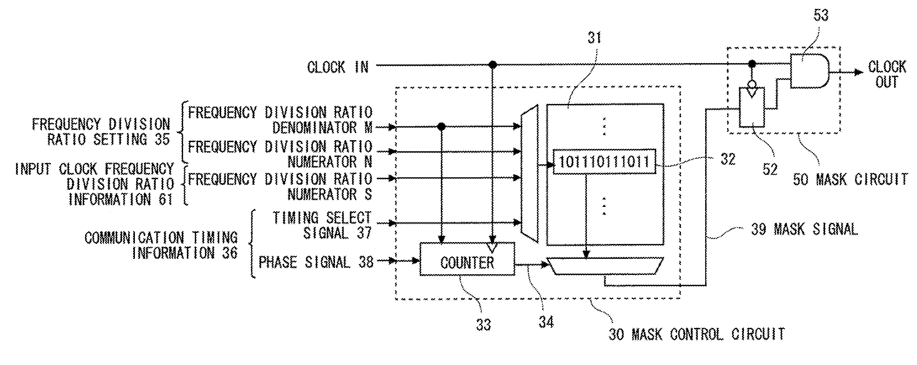
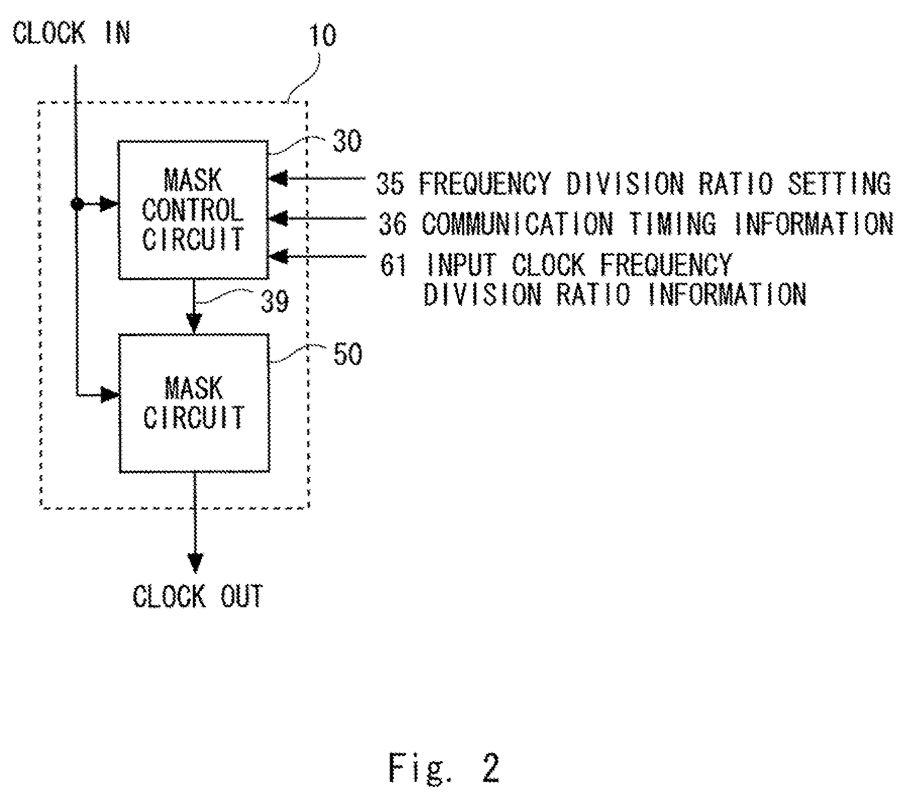
[0083]Next, a clock frequency divider circuit in accordance with a second exemplary embodiment of the present invention is explained with reference to FIG. 5. FIG. 5 is a block diagram of a clock frequency divider circuit in accordance with the second exemplary embodiment of the present invention. In the second exemplary embodiment of the present invention, specific examples of the mask circuit 50 and the mask control circuit 30 of the clock frequency divider circuit 10 in accordance with the first exemplary embodiment are explained.

[0084]In FIG. 5, the mask circuit 50 has a function of selecting whether a clock IN pulse is masked or is output as the clock OUT without being masked by referring to an input mask signal 39. In the second exemplary embodiment, this mask circuit 50 includes a latch circuit 52 and a gate circuit 53.

[0085]The latch circuit 52 has a function of restricting the transition of the mask signal 39 that is input to the gate circuit 53 to timings at which the valu...


PUM


Abstract

To provide a clock frequency divider circuit that generates a clock signal enabling an expected proper communication in communication with a circuit operating by a clock having a different frequency. A clock frequency division circuit according to the present invention generates an output clock signal obtained by dividing a frequency of an input clock signal into N / S by subtracting (S−N) clock pulses from S clock pulses of the input clock signal based on a frequency division ratio defined as N / S. The clock frequency division circuit generates a control signal used to preferentially subtract a clock pulse at a timing other than a communication timing of data communication performed by a target circuit using the output clock signal among S clock pulses of the input clock signal. Further, it generates the output clock signal by subtracting a clock pulse of the input clock signal according to the generated control signal.

Description

[0001]This application is the National Phase of PCT / JP2009 / 003631, filed Jul. 30, 2009, which is based upon and claims the benefit of priority from Japanese patent application No. 2008-278497, filed on Oct. 29, 2008, the disclosure of which is incorporated herein in its entirety by reference.TECHNICAL FIELD[0002]The present invention relates to a clock frequency divider circuit, a clock distribution circuit, a clock frequency division method, and a clock distribution method. In particular, the present invention relates to a clock frequency divider circuit, a clock distribution circuit, a clock frequency division method, and a clock distribution method to generate clock signals having different frequencies and distribute generated clock signals having different frequencies to respective functional blocks.BACKGROUND ART[0003]As a method for distributing a clock signal having a different frequency to each of a plurality of circuits (functional blocks) integrated in one semiconductor de...

Claims


Application Information

Patent Timeline
Patent Type & Authority Patents(United States)
IPC IPC(8): H03K21/00
CPCG06F1/04H03B19/00H03K23/662H03K5/1506
Inventor SHIBAYAMA, ATSUFUMI
Owner NEC CORP
Features
  • R&D
  • Intellectual Property
  • Life Sciences
  • Materials
  • Tech Scout
  • Unparalleled Data Quality
  • Higher Quality Content
  • 60% Fewer Hallucinations
Learn More