
Apparatus for controlling the energizing of a heater

a technology for energizing and control apparatus, which is applied in the direction of adaptive control, electric control, instruments, etc., can solve the problems of difficulty in maintaining the temperature of the heating resistor, and the accuracy of calibration may drop, so as to achieve accurate performance, high accuracy of acquired second resistance, and consumption of energy accumulated during the operation of the internal combustion engine

Inactive Publication Date: 2013-04-16
NGK SPARK PLUG CO LTD
View PDF41 Cites 8 Cited by
  • Summary
  • Abstract
  • Description
  • Claims
  • Application Information

AI Technical Summary

Benefits of technology

The present invention relates to a heating system for an internal combustion engine, which uses electricity to heat the engine during operation. The invention aims to improve the accuracy of detecting the exchange of the heater, while also reducing energy consumption during periods of engine dormancy. The invention achieves this by performing a calibration of the heating resistor while the engine is stopped and supplying electricity to the heating resistor only when necessary. This reduces the amount of energy consumed during the calibration process. Additionally, the invention includes a heater energization control apparatus that can detect the exchange of the heater by itself, without the need for additional sensors or calibration. This allows for accurate control of the heating resistor temperature and ensures reliable detection of heater exchange.

Problems solved by technology

However, maintaining the temperature of the heating resistor is difficult when the heating resistor is thermally influenced from the outside; e.g., when the heating resistor is cooled by a disturbance.
However, when the engine is cranked (started) in the middle of the pre-heating of the glow plug; i.e., in the middle of the calibration, a disturbance, such a swirl within the engine, injection of fuel, or the like, arises, and the heating resistor is partially cooled, whereby the accuracy of the calibration may drop.

Method used


Image

  • Apparatus for controlling the energizing of a heater
  • Apparatus for controlling the energizing of a heater
  • Apparatus for controlling the energizing of a heater

Examples


Embodiment Construction

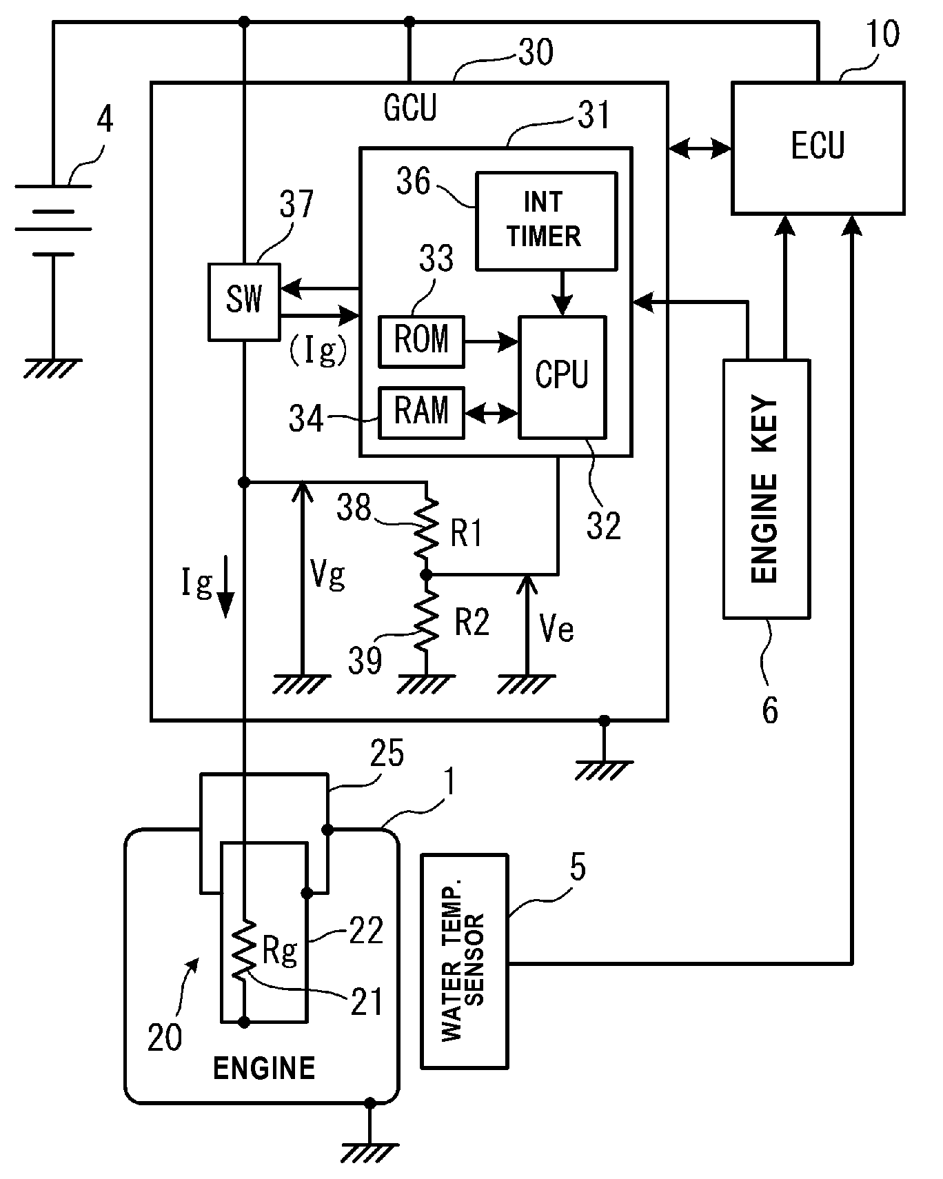
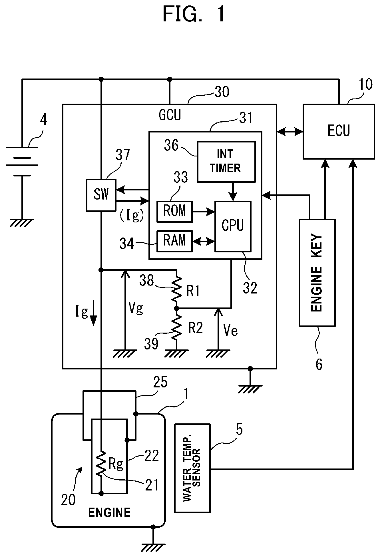
[0036]One embodiment of a heater energization control apparatus according to the present invention will now be described with reference to the drawings. In the present embodiment, a glow plug 20 which is used for assisting startup of a diesel engine (hereinafter, simply referred to as the “engine”) 1 of an automobile and for improving operation stability of the engine is mentioned as an example of a heater, and a glow control apparatus (GCU) 30 which controls energization of the glow plug will be described as an example of the energization control apparatus. Notably, the accompanying drawings are used so as to describe technical features which the present invention can employ; the structure of the apparatus, flowcharts of various processings, etc. which are described herein are mere illustrative examples; and the present invention is not limited thereto unless stated otherwise.

[0037]First, the schematic configuration of a system in which the GCU 30 controls energization of the glow ...


PUM


Abstract

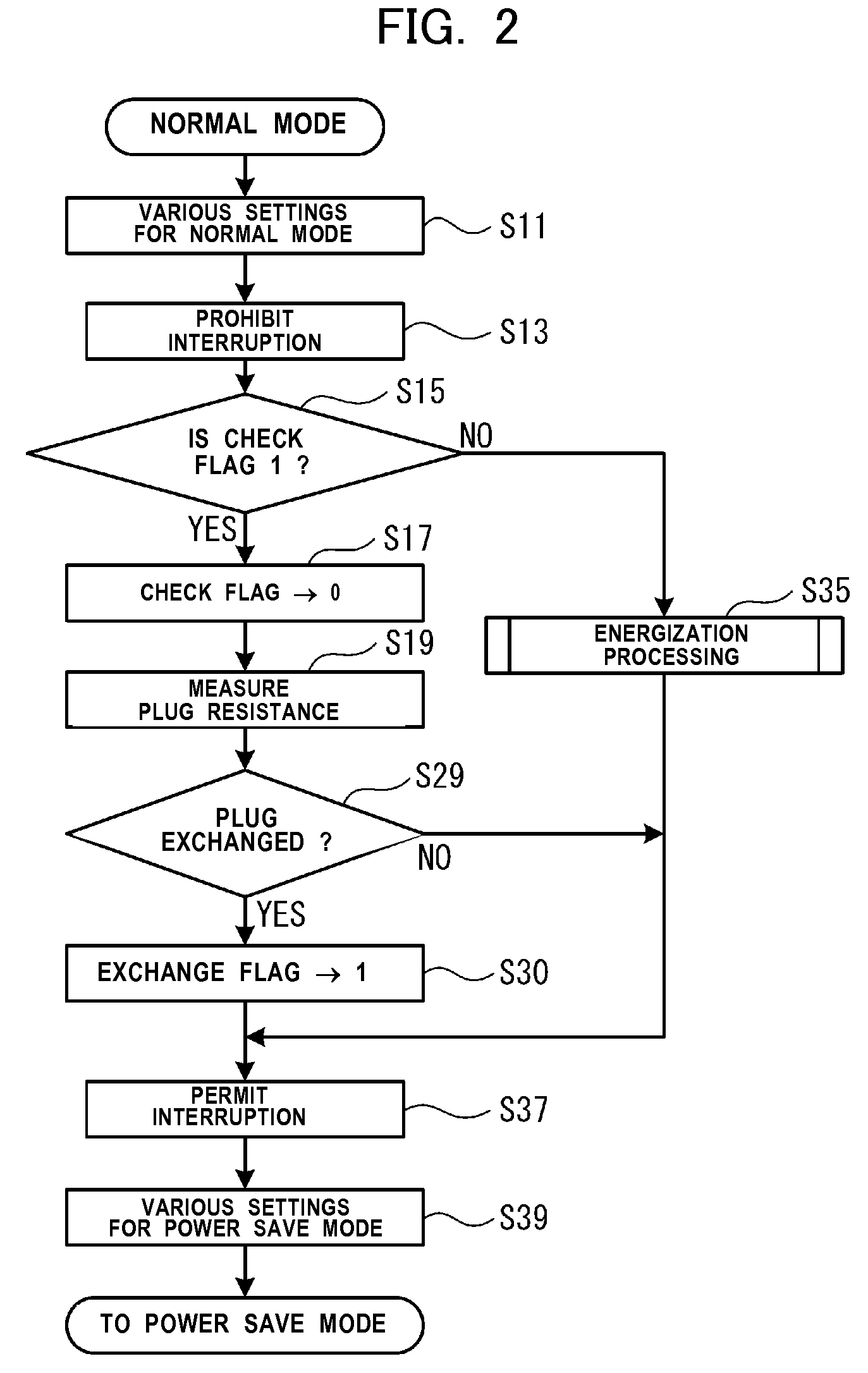
A heater energization control apparatus. When an engine is stopped, a microcomputer of a GCU enters a power save mode. When the microcomputer returns to a normal mode in response to an interruption signal periodically generated from an interruption timer, the microcomputer supplies electricity to a heating resistor for a short time and obtains its resistance (S19). When the resistance is greater than a first reference value, the microcomputer determines that a glow plug is removed from the engine; that is, the glow plug is being exchanged (S29). The microcomputer sets an exchange flag to “1” (S30), and performs calibration for the heating resistor of a new glow plug after the engine is operated next time (S35). When the current resistance becomes smaller than the past resistance, the microcomputer determines that the glow plug has been exchanged.

Description

TECHNICAL FIELD[0001]The Present invention relates to a heater energization control apparatus for controlling energization of a heater having a heating resistor which generates heat upon supply of electricity thereto.BACKGROUND ART[0002]Conventionally, in an automobile, a heater having a heating resistor which generates heat upon supply of electricity thereto is used, in combination with an energization control apparatus for performing energization control for the heater, in order to assist startup of an engine, stably operate the engine, or heat the compartment of the automobile. Further, a widely used heating resistor has a positive correlation between temperature and resistance such that resistance increases with temperature. Examples of known schemes for controlling supply of electricity to a heater having such a heating resistor include a constant power control scheme and a resistance control scheme.[0003]In the constant power control scheme, the electric power supplied to the ...

Claims


Application Information

Patent Timeline
IPC IPC(8): G05D23/19
CPCF02P19/027F02P19/025F02D41/042F02D41/2464
Inventor SAKURAI, TAKAYUKIOHTANI, TAKAYUKITSUCHIYA, HIROKI
Owner NGK SPARK PLUG CO LTD
Learn More