Method for manufacturing an electric machine by a lost foam casting process, and electric machine for a hybrid vehicle

a foam casting and electric machine technology, applied in the direction of manufacturing tools, foundry patterns, moulding apparatus, etc., can solve the problems of widening the functional air gap between the rotor and the stator, limiting flexibility, etc., and achieve the effect of maximum flexibility of the housing

Active Publication Date: 2013-04-23
ROBERT BOSCH GMBH
View PDF15 Cites 4 Cited by
  • Summary
  • Abstract
  • Description
  • Claims
  • Application Information

AI Technical Summary

Benefits of technology

[0007]The method according to the present invention for manufacturing an electric machine and the electric machine manufactured according to the method of the present invention allow for the achievement of a maximum flexibility of the housing with respect to specified interfaces.
[0008]The method of the present invention for manufacturing the electric machine having the features described herein provides for a housing of the electric machine to be manufactured in the following method steps. The manufacture of a housing foam part from at least three individual foam parts, the use of at least three individual foam parts offering the possibility of manufacturing the housing foam part according to a modular design principle, which keeps the number of necessary tools for manufacturing the foam parts low and saves costs in the manufacture. The more variants there are of the final product, the more costs may be saved if the same tools may be used for several variants. Manufacturing the housing foam part in individual foam parts offers the advantage of manufacturing it in a disk construction, for example made up of a center disk, an annular disk and a bearing support disk. In contrast to manufacturing the housing foam part from a single tall tool, the individual foam parts are manufactured in shallower tools, whereby the casting method is optimized and thereby also made more cost-effective.
[0009]Another method step for manufacturing the housing of the electric machine is the manufacture of a housing cast blank using the housing foam part according to a lost-foam casting method. The lost-foam casting method offers innovative possibilities of component design in that individual foam parts are joined to form a single housing foam part. In addition, the casting method also offers a high modification flexibility with respect to the individual foam parts, which is advantageous for the diversity of variants of the housing.

Problems solved by technology

A disadvantage in this construction is a long tolerance chain between the two bearings, which results in a widening of the functional air gap between the rotor and the stator, or requires a very narrow tolerance field for manufacturing the three individual housing parts.
Two-part housings allow for a manufacture at a wider tolerance field while maintaining a constant air gap, but are limiting with respect to flexibility and the fulfillment of varying requirements because the housings must be adapted almost entirely; for example in the event of modifications of possible predefined interfaces such as coolant or high-voltage terminals.

Method used


Image

  • Method for manufacturing an electric machine by a lost foam casting process, and electric machine for a hybrid vehicle
  • Method for manufacturing an electric machine by a lost foam casting process, and electric machine for a hybrid vehicle
  • Method for manufacturing an electric machine by a lost foam casting process, and electric machine for a hybrid vehicle

Examples


first embodiment

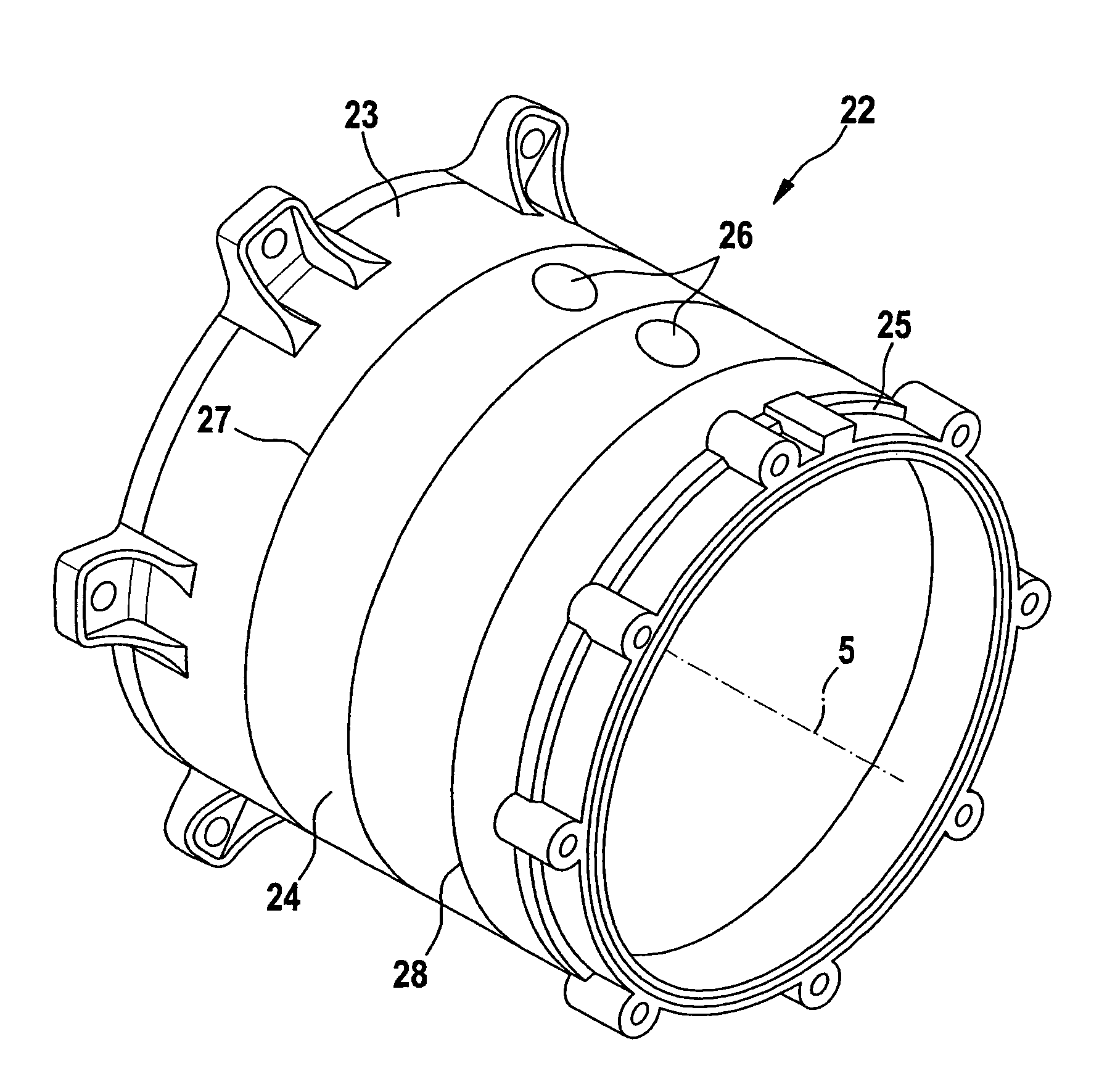
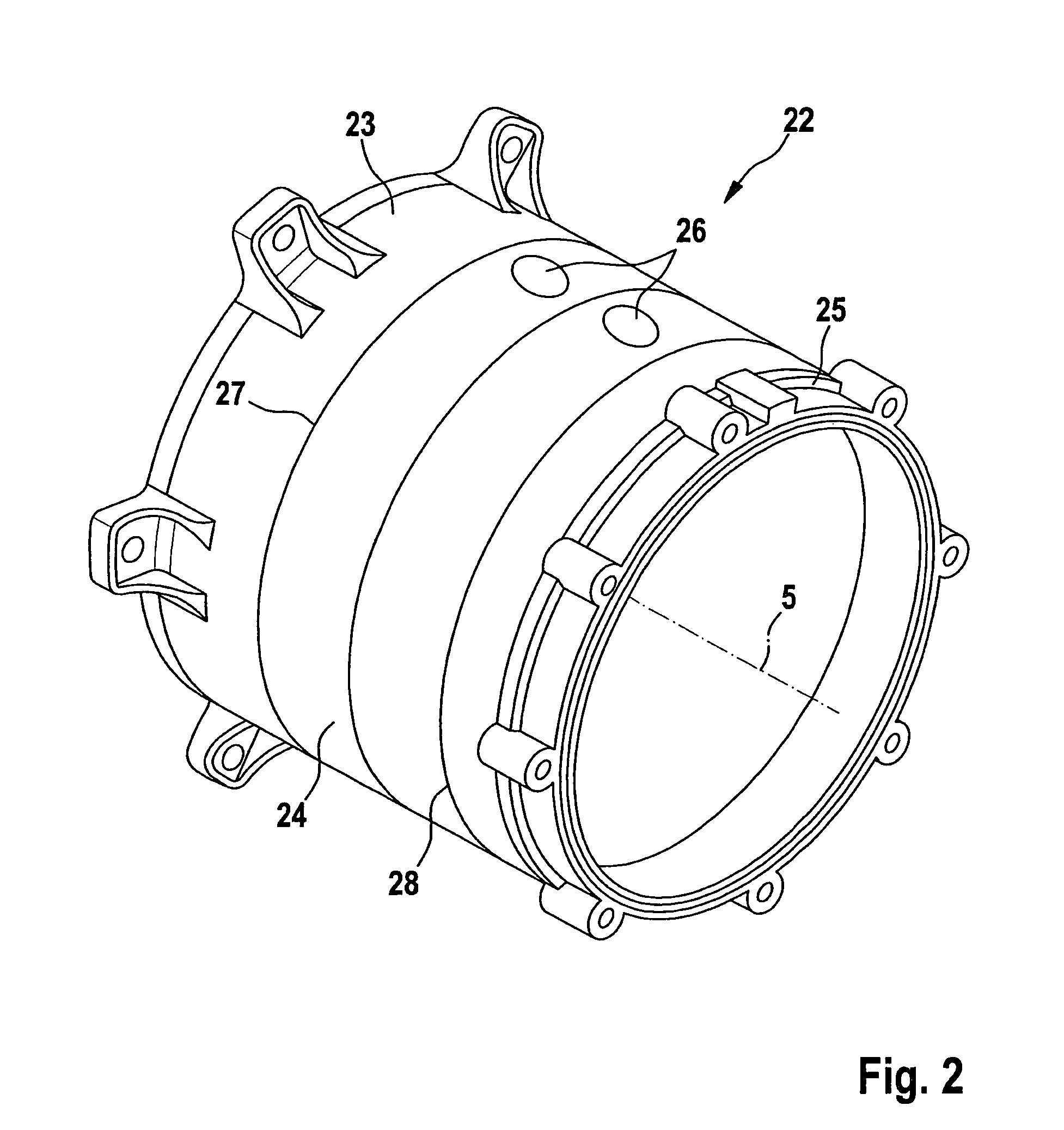
[0040]FIG. 2 shows a perspective representation of a housing foam part 22 of the present invention. Housing foam part 22 is formed from three individual foam parts 23, 24, 25, which are joined by a bonding method coaxially to rotor axis 5. The individual foam parts 23, 24, are a bearing support disk 23, a center disk 24 having integrated openings 26, and an annular disk 25. In the bonding method, the individual foam part of bearing support disk 23 is bonded to the individual foam part of center disk 24 at a first bond seam 27. The individual foam part of annular disk 25 is subsequently bonded to center disk 24 at a second bond seam 28. Alternatively, annular disk 25 may also be bonded first to center disk 24, and bearing support disk 23 may be subsequently bonded to center disk 24.

[0041]Individual foam parts 23, 24, 25 are shown in FIGS. 3, 4 and 5 and described in more detail below. FIG. 3 shows a perspective representation of the cup-shaped individual foam part of bearing support ...

second embodiment

[0051]FIG. 10b) shows a top view on ring side 9 of housing 102. The representation is analogous to FIG. 10a) except that second annular part 136 is situated at a greater angle β with respect to coolant connector 16 than angle α in FIG. 10a). For the representation, a third reference line 51 is drawn through shoulder 50 and rotor axis 5. Compared to housing 2 shown in FIG. 10a), second annular part 136 of housing 102 is cast in this embodiment rotated by angle (β-α).

third embodiment

[0052]FIG. 11 shows a perspective view of a housing foam part 222 of a third embodiment having an extended bearing support disk 223. For manufacturing this extended bearing support disk 223, a tool changed in length is produced for manufacturing the foam part. Housing foam part 222 is manufactured as described in FIG. 2 in that unmodified center disk 24 is bonded to extended bearing support disk 223 coaxially to rotor axis 5, and subsequently annular disk 25 is bonded to center disk 24.

[0053]Another possibility of axially lengthening housing foam part 22 and as a result housing 2 is to extend the individual foam parts of annular disk 25 and there specifically first annular foam part 35. Depending on the construction and requirement of electric machine 1 it is useful to extend axially only one individual foam part 23, 25 or both individual foam parts 23, 25. Center disk 24, from which center part 124 is removed after casting, is kept constant in its axial extension.

[0054]Defining hou...


PUM

PropertyMeasurementUnit
flexibilityaaaaaaaaaa
voltageaaaaaaaaaa
shapeaaaaaaaaaa

Abstract

A method for manufacturing an electric machine, made up of a housing, a stator accommodated in the housing, which is formed from a stator body and stator windings, a rotor, which is supported in the housing so as to be rotatable about a rotor axis, and a bearing support fastened on the housing, includes a housing foam part manufactured from at least three individual foam parts and a housing cast blank manufactured using the housing foam part in accordance with a lost foam casting method. Individual foam parts are made up of a center disk having an essentially hollow-cylindrical design and forming an intermediate piece of a housing foam part, an annular disk having an essentially hollow-cylindrical design and forming another intermediate piece of the housing foam part, and a bearing support disk having an essentially cup-shaped design and forming an end of the housing foam part.

Description

FIELD OF THE INVENTION[0001]The present invention relates to a method for manufacturing an electric machine and to an electric machine.BACKGROUND INFORMATION[0002]In current designs of electric machines, the housing predominantly has a multipart construction. In particular, two designs are used in this connection. First, there is a three-part design of the housing as in DE 1 765 059 U, and second, there is a two-part design as in EP 1 041 699 B1.[0003]The three-part design is made up of a central cylindrical body, in which the stator of the electric machine is accommodated, and two bearing supports, which terminate the housing on both sides. The bearing supports accommodate a floating bearing or a fixed bearing. A disadvantage in this construction is a long tolerance chain between the two bearings, which results in a widening of the functional air gap between the rotor and the stator, or requires a very narrow tolerance field for manufacturing the three individual housing parts.[000...

Claims


Application Information

Patent Timeline
Patent Type & Authority Patents(United States)
IPC IPC(8): H02K15/00
CPCB22C7/026B22C9/046H02K5/20H02K15/14H02K5/06Y10T29/49009H02K5/203
Inventor KERN, DENISHERZBERGER, ANDREAS
Owner ROBERT BOSCH GMBH
Why Eureka
Try Eureka