
Pressure regulator

Active Publication Date: 2013-04-23
ROWE CARROLL G
View PDF16 Cites 4 Cited by
  • Summary
  • Abstract
  • Description
  • Claims
  • Application Information

AI Technical Summary

Benefits of technology

The present invention is a pressure regulator that helps reduce the pressure of high-pressure water from a hydrant or other source before it enters a CAFS pump. This allows the high-pressure water to be used directly without needing to first route it through a tank or use a bleed-off relief valve. The pressure regulator also allows the CAFS to operate with lower-pressure water sources if desired. This invention ensures that firefighters can use any available water source without worrying about the quality of the resulting foam.

Problems solved by technology

CAFS may be particularly valuable for rural fire departments, because the use of foam reduces the amount of water required to extinguish a fire, and rural departments are often quite limited in the amount of water that they have available at any particular fire.
A persistent challenge with CAFS design is the maintenance of a correct balance between incoming water and air pressure.
If these pressures are not correctly balanced, a low-quality foam or no foam at all may result.
Such systems cannot be effectively employed with direct feed from a high-pressure source, such as a typical fire hydrant.
The reason for this is that the centrifugal pump used to create water pressure in such systems boosts the incoming water pressure, and the result is that the vehicle's engine RPM necessary for satisfactory water pressure will be insufficient to produce the required volume of air for production of satisfactory CAFS.
Thus if the incoming water pressure from the water source is higher than approximately 20 psi, the system would be incapable of producing a properly balanced, high-quality firefighting foam because there is no means of lowering the incoming water pressure with a centrifugal pump.
But the result of using a bleed-off relief valve is wasted water, which may be a particularly critical concern for rural fire departments, where utilization of all available water may be essential for many firefighting efforts.
Otherwise, as the CAFSPro system User Operation Manual explains, “[i]f incoming water pressure is excessively high, it may not be possible to maintain engine RPM and desired pressure.” Another means is to attempt to gate the incoming water stream to match the required volume, but this is not an acceptable means, for if a nozzle at any discharge is closed or opened it adversely affects the system pressure, so the pump will either be starved for water and have insufficient volume and pressure, or a pressure spike will occur that is above an acceptable threshold before the pump operator can adjust the incoming flow.
The manual approach to water tank level management ties up a firefighter that could otherwise perform other critical tasks, which is an especially important issue for rural fire departments with limited manpower.
The automated approach requires the addition of expensive equipment, which again is a particular concern for rural fire departments since the price of such equipment may not be within their limited equipment budgets.

Method used


Image

  • Pressure regulator
  • Pressure regulator

Examples


Embodiment Construction

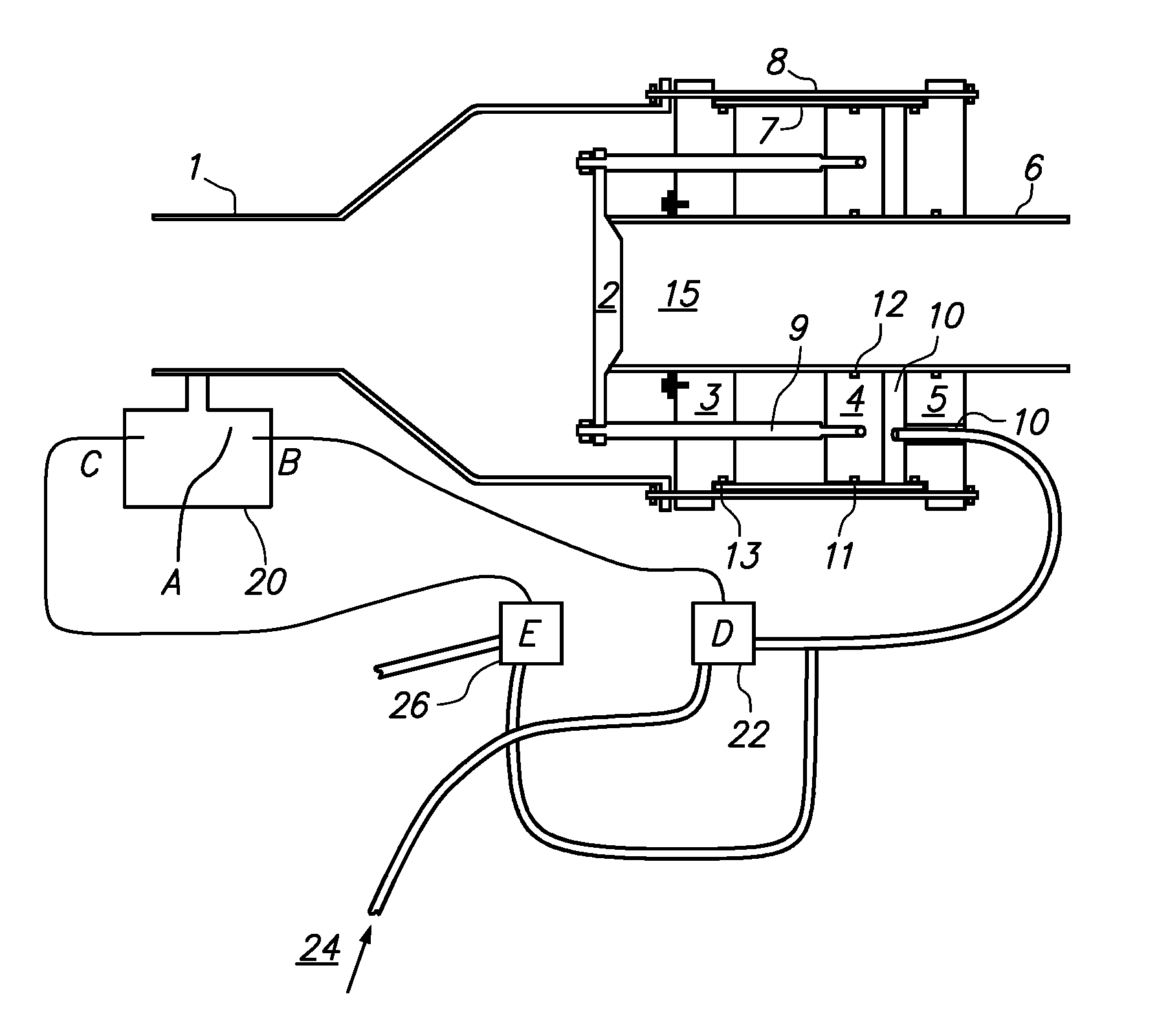
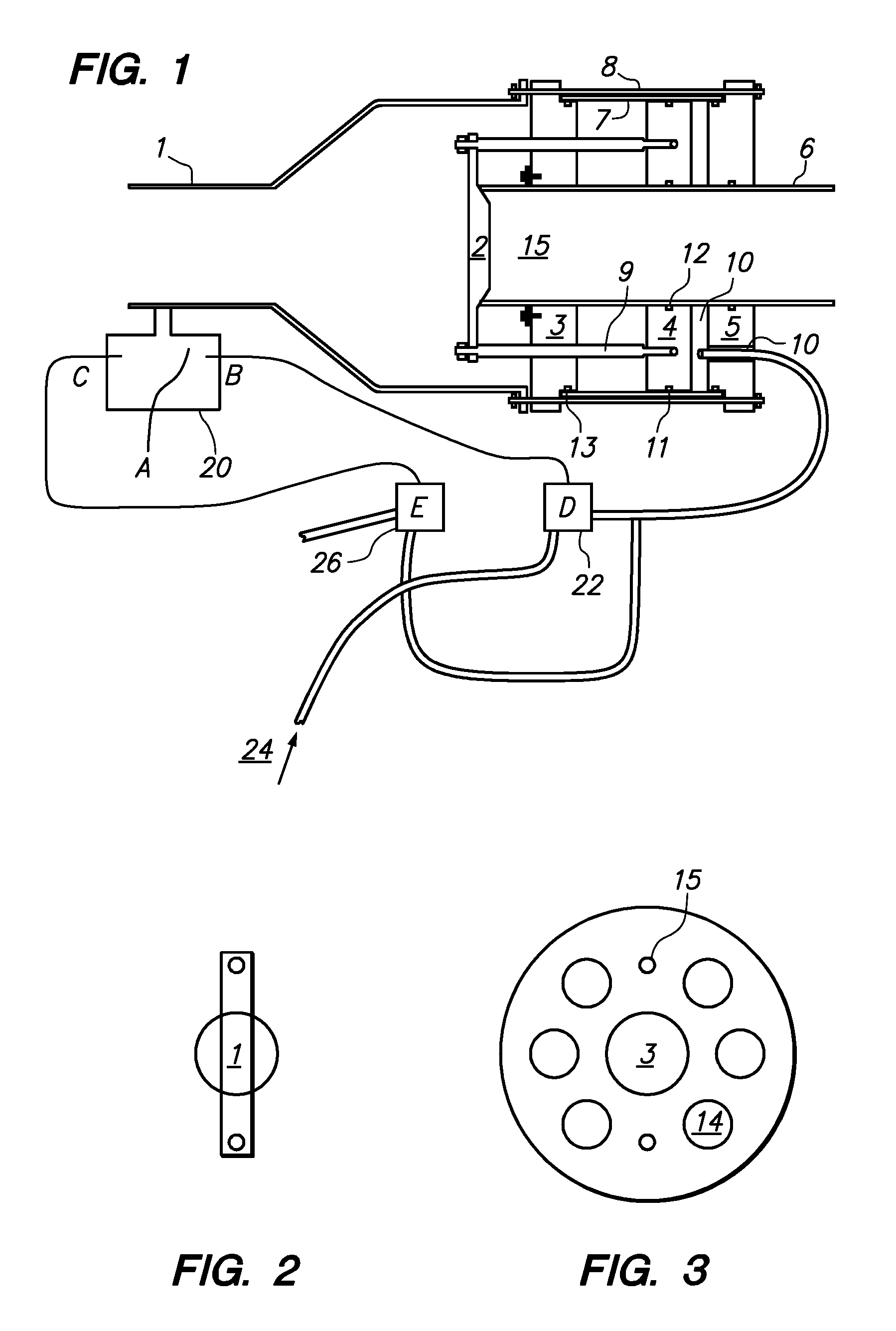
[0015]With reference now to FIGS. 1-3, a preferred embodiment of the present invention may be described. Liquid, preferably water, enters the regulator from a hydrant or other high-pressure source at inlet 6. Discharge chamber 1 may be preferably connected to a CAFS (not shown), many types of which are known in the art and fall within the scope of the invention. Regulating the flow of liquid between inlet 6 and discharge chamber 1 is valve 2. In the closed position, as shown in FIG. 1, valve 2 completely blocks the flow of liquid out of inlet 6 by seating itself at the outflow end of inlet 6. When valve 2 is open, however, liquid may flow around the periphery of valve 2 from inlet 6 into discharge chamber 1. From discharge chamber 1, liquid may enter the CAFS system where it is mixed with air and surfactant to produce foam in a manner as known in the art.

[0016]Connecting links 9 attach valve 2 to piston 4. Two connecting links 9 are shown in the cut-away view of FIG. 1, but any numb...


PUM


Abstract

A pressure regulator is capable of automatically regulating the inlet water pressure to a compressed air foam system (CAFS), thereby allowing direct connection between a high-pressure water source, such as a hydrant, and the CAFS. The pressure regulator includes an inlet, a valve that regulates flow from the inlet, and an annular piston that circumscribes the inlet and which is linked to the valve. The relative area of the inlet and the piston determine the maximum pressure that may be attained at the CAFS water inlet, due to pressure on the piston forcing the valve closed.

Description

CROSS-REFERENCE TO RELATED APPLICATIONS[0001]The present application claims the benefit of U.S. provisional patent application Nos. 61 / 155,245, filed on Feb. 25, 2009, and 61 / 171,679, filed on Apr. 22, 2009. The entire disclosure of each such provisional patent application is hereby fully incorporated by reference.STATEMENT REGARDING FEDERALLY SPONSORED RESEARCH OR DEVELOPMENT[0002]Not applicable.BACKGROUND OF THE INVENTION[0003]Compressed air foam systems (CAFS) have been used in firefighting for quite some time. The original CAFS developments were made by the U.S. Navy during the 1940's as a method to fight fires on board ships. In its most basic form, CAFS is simply a means for mixing air and water with a surfactant in order to produce a water-based foam that is used to extinguish fires. CAFS provides quicker “knockdown” against potent fires, deeper penetration of fuels, and gives firefighters the advantage of making their initial attack against a fire from a significantly greate...

Claims


Application Information

Patent Timeline
IPC IPC(8): F16K31/12F16K31/36
CPCA62C5/02F16K31/1226F16K1/126G05D16/106G05D16/2093G05D16/2097Y10T137/7834Y10T137/7808Y10T137/7762Y10T137/7811Y10T137/7793
Inventor ROWE, CARROLL G.
Owner ROWE CARROLL G
Learn More