Antenna and RFID device

a technology of rfid and antenna coil, which is applied in the direction of loop antennas, radiating element structure forms, instruments, etc., can solve the problems of difficult reading and writing, difficult to enhance the degree of coupling between the antenna coil and the booster coil, and large outside dimension of the booster coil, etc., to achieve superior transmission efficiency and high coupling

Active Publication Date: 2013-04-23
MURATA MFG CO LTD
View PDF597 Cites 15 Cited by
  • Summary
  • Abstract
  • Description
  • Claims
  • Application Information

AI Technical Summary

Benefits of technology

[0010]Accordingly, preferred embodiments of the present invention provide an antenna that has a high degree of coupling between a feed coil and a booster antenna and superior transmission efficiency of an RF signal and also prevents the occurrence of a null point, and also provide an RFID device including the antenna.

Problems solved by technology

Therefore, it is difficult to enhance the degree of coupling between the antenna coil and the booster coil.
In addition, while, in Japanese Unexamined Patent Application Publication No. 2002-042083, a structure is disclosed in which the shape of a portion that is included in the booster coil and in which the RFIC chip is mounted, is turned into a shape closely related to the antenna coil, thereby enhancing the degree of coupling between the antenna coil on an RFIC chip side and the booster coil, the shape of the booster coil tends to become complex and the outside dimension of the booster coil tends to become large, in this structure.
At this null point, it is hard to perform reading and writing.

Method used


Image

  • Antenna and RFID device
  • Antenna and RFID device
  • Antenna and RFID device

Examples


first preferred embodiment

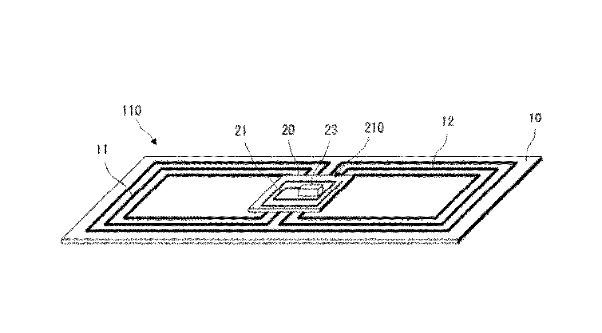
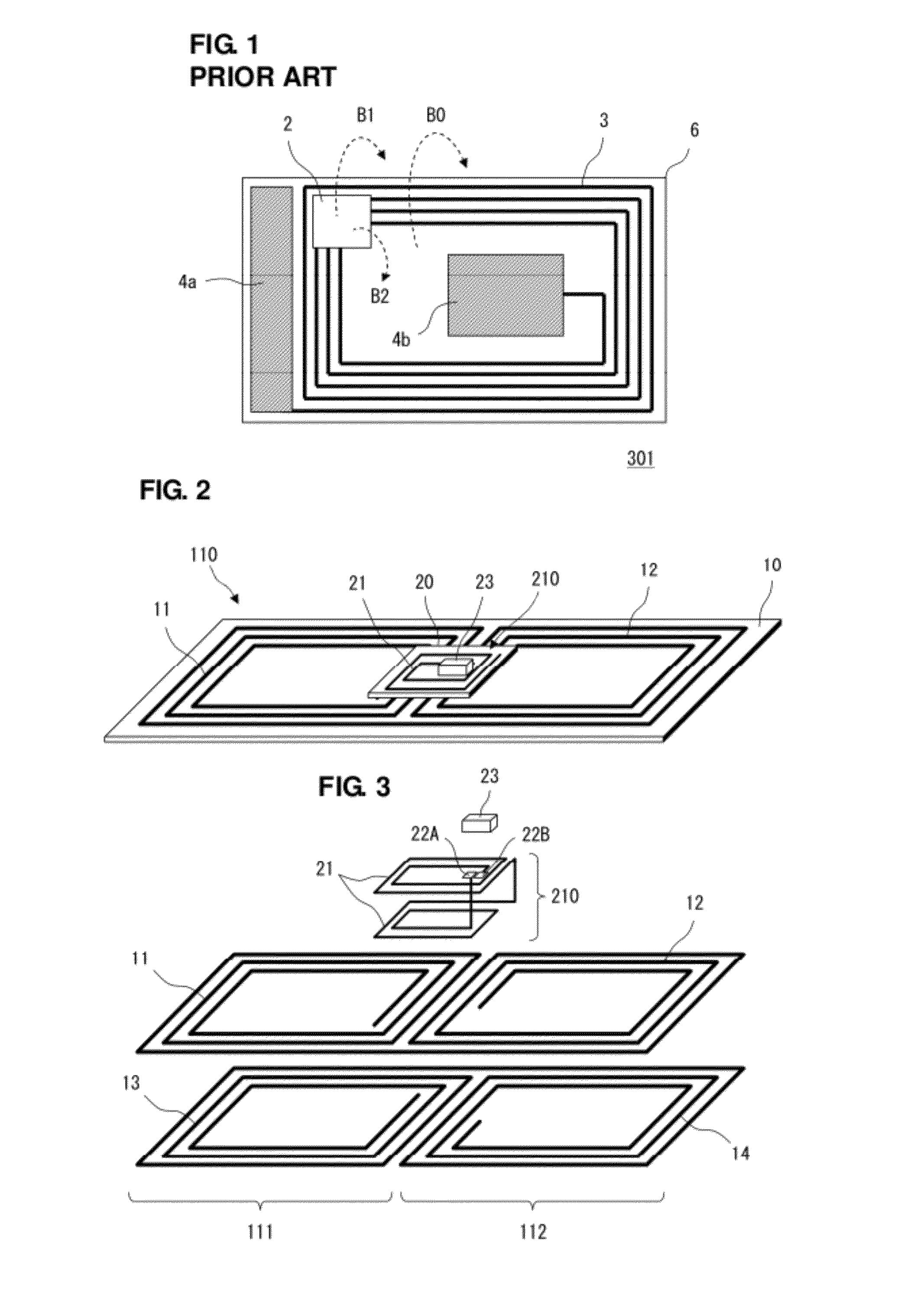
[0038]FIG. 2 is the perspective view of an RFID device 301 according to a first preferred embodiment of the present invention. FIG. 3 is the exploded perspective view of a portion other than the base material of a feed antenna and the base material of a booster antenna. This RFID device 301 is preferably used as an RFID tag used for an RFID system of an HF band. For example, the RFID device 301 may preferably be included in a portable electronic device.

[0039]As illustrated in FIG. 2, the RFID device 301 includes an RFIC chip 23, a feed antenna 210 connected to the RFIC chip 23, and a booster antenna 110 coupled to the feed antenna 210.

[0040]The RFIC chip 23 preferably is an IC chip used for RFID, includes a memory circuit, a logic circuit, a clock circuit, and the like, and is preferably configured as an integrated circuit chip processing an RF signal.

[0041]The feed antenna 210 includes a feed antenna base material 20, a feed coil 21, and an RFIC chip 23. In the feed coil 21, rectan...

second preferred embodiment

[0060]FIG. 7 is the exploded perspective view of an RFID device 302 according to a second preferred embodiment of the present invention.

[0061]This RFID device includes an RFIC chip 23, a feed antenna 210 connected to the RFIC chip 23, and a booster antenna 120 coupled to the feed coil 21 of the feed antenna 210. In FIG. 7, the base material of the feed antenna 210 is not illustrated.

[0062]In the second preferred embodiment, a coil 11 is a first booster coil, and a coil 12 is a second booster coil.

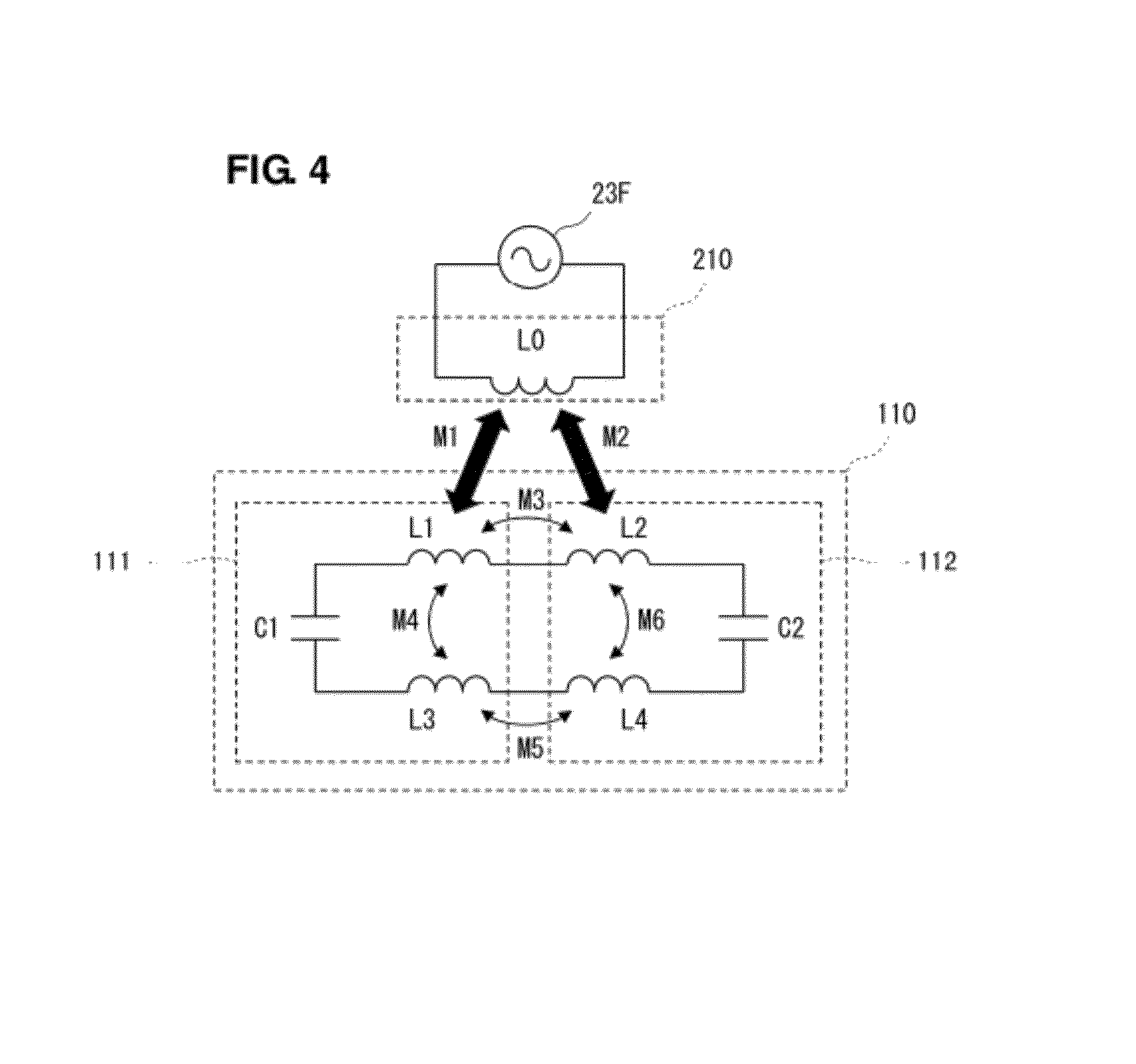
[0063]FIG. 8 is the equivalent circuit diagram of an antenna portion of the RFID device 302. Here, an inductor L0 corresponds to the feed coil 21, a feed circuit 23F is the feed circuit of the RFIC chip 23. In addition, inductors L1 and L2 correspond to the coils 11 and 12, respectively. A capacitor C1 corresponds to line-to-line distributed capacitance based on the coils 11 and 12 or capacitance in a pattern.

[0064]In this way, the booster antenna may be configured only using two coils 11 a...

third preferred embodiment

[0065]FIG. 9 is the perspective view of an RFID device 303 according to a third preferred embodiment. FIG. 10 is the exploded perspective view of the RFID device 303. In this regard, however, in any one of FIG. 9 and FIG. 10, the base material of a booster antenna is omitted, and a conductor portion is only illustrated.

[0066]This RFID device 303 includes a feed antenna 220 and a booster antenna 130 coupled to the feed antenna 220.

[0067]The feed antenna 220 includes a feed antenna base material 20, a feed coil 21, and an RFIC chip 23. In the feed coil 21, rectangular spiral-shaped conductor patterns of a plurality of turns are provided in a plurality of layers. The RFIC chip 23 is connected to both end portions of this feed coil 21.

[0068]The booster antenna 130 preferably includes a first booster coil 121 and a second booster coil 122. The first booster coil 121 preferably includes a coil 11 and a coil 13, and the second booster coil 122 preferably includes coils 12 and 14 and pad el...


PUM


Abstract

In an antenna for an RFID device, a feed coil is coupled to a first booster coil and a second booster coil through an electromagnetic field. In the feed coil, a first region and a second region are disposed so as to overlap with the first booster coil and the second booster coil, respectively. The first region of the feed coil is coupled to the first booster coil through an electromagnetic field, and the second region of the feed coil is coupled to the second booster coil through an electromagnetic field. Accordingly, the antenna has a high degree of coupling between the feed coil and a booster antenna and superior transmission efficiency of an RF signal, and prevents the occurrence of a null point.

Description

BACKGROUND OF THE INVENTION[0001]1. Field of the Invention[0002]The present invention relates to an antenna preferably for use in a wireless communication system such as an RFID (Radio Frequency Identification) system, and an RFID device including the antenna, and, in particular, relates to an antenna and an RFID device, applied to an RFID system of an HF band.[0003]2. Description of the Related Art[0004]In recent years, as a wireless communication system for performing information management of articles, an RFID system has been put to practical use, the RFID system establishing communication between a reader / writer generating an induction magnetic field and an RFID tag attached to an article on the basis of a non-contact method utilizing an electromagnetic field, and transmitting predetermined information. Here, the RFID tag includes an RFIC chip storing therein predetermined information and processing a predetermined RF signal and an antenna transmitting and receiving the RF signa...

Claims


Application Information

Patent Timeline
Patent Type & Authority Patents(United States)
IPC IPC(8): G06K19/00
CPCH01Q1/2216H01Q1/38H01Q5/378H01Q1/2225H01Q7/00
Inventor KATO, NOBORU
Owner MURATA MFG CO LTD
Why Eureka
Try Eureka