Cooling system

Active Publication Date: 2013-04-23
JCA TECH
View PDF19 Cites 34 Cited by
  • Summary
  • Abstract
  • Description
  • Claims
  • Application Information

AI Technical Summary

Benefits of technology

[0032]Regardless of the amount of air supplied to the front face of the server, it will only ever draw across it the design flow rate of its internal fans. This point is stressed again bec

Problems solved by technology

The disadvantages of the downflow CRAC unit method are that is cools the room, not just the ICT rack, it is not controlled at the ICT rack level and that it moves more air than is required and at temperatures that do not suit ICT equipment which will be further explained later.
Disadvantages are that redundancy is required at the rack level which means that N+1 (the most popular configuration) is exactly the same solution as 2N.
Another disadvantage is that the secondary cooling medium has to be run within the data centre.
Some data centre operators are understandably nervous about moving large quantities of water or high p

Method used


Image

  • Cooling system
  • Cooling system
  • Cooling system

Examples


Embodiment Construction

[0032]Regardless of the amount of air supplied to the front face of the server, it will only ever draw across it the design flow rate of its internal fans. This point is stressed again because it is instrumental to the new invention's effectiveness that works in harmony with the ICT equipment not in isolation to it and in doing so provides large energy saving opportunities.

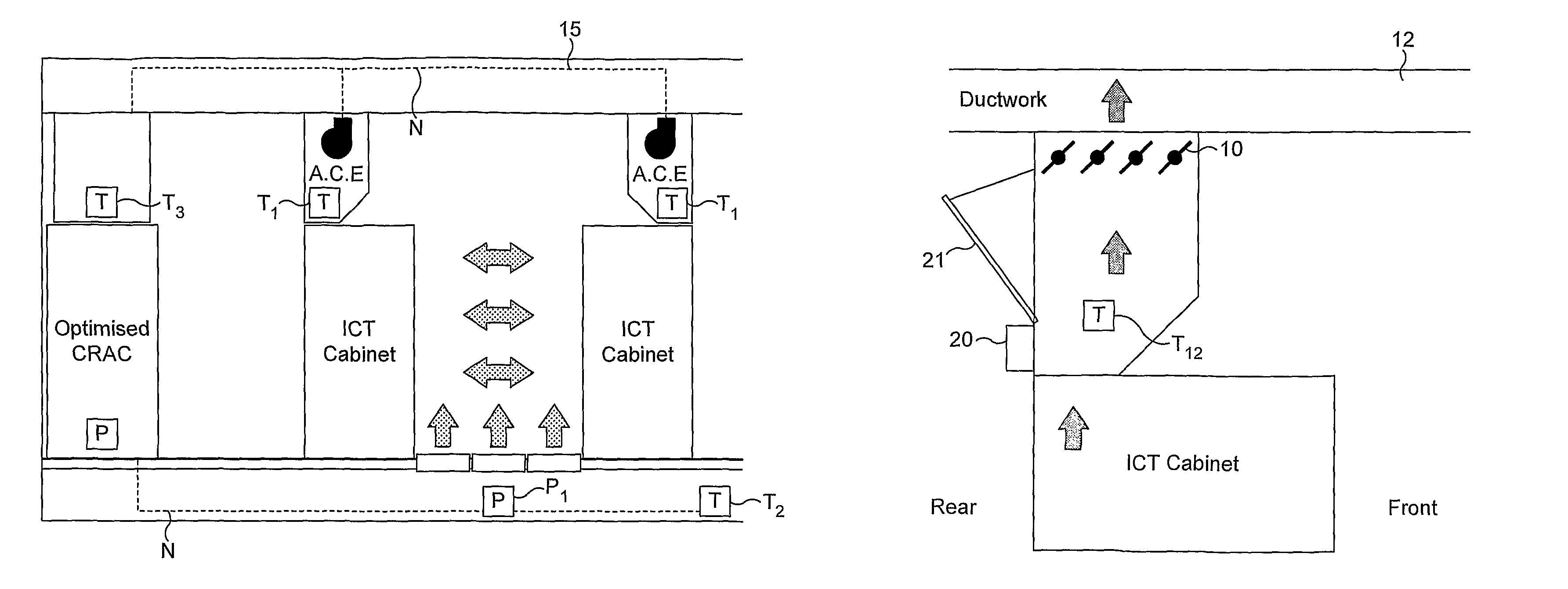
[0033]The present invention arose in an attempt to provide performance similar to that of the rack cooler but with the flexibility and benefits of CRAC systems.

[0034]The present invention arose from the understanding that ICT (Information Communication Technology) equipment, servers, routers, switches etc have a cooling design and philosophy of their own. Each item of ICT equipment that is air cooled (majority of ICT equipment) will generally have one or more heat sinks complete with fans to dissipate the heat energy produced as part of their operation.

[0035]With these facts in mind, the cooling solution is design...


PUM


Abstract

A system for cooling an environment housing a plurality of electronic equipment in one or more cabinets is disclosed, the system comprising a remote cooling unit(s) adapted to provide relatively cool air into the environment, an exhaust associated with each cabinet, the exhaust being provided with variable airflow means; the remote unit being adapted to receive exhausted air, and; sensor means adapted to determine cooling demand and alter the output of the remote cooling unit(s) accordingly. Schemes for using the system are described.

Description

BACKGROUND[0001]1. Field of the Disclosure[0002]This invention relates to a cooling system for cooling data centres (i.e. environments where a plurality of IT equipment, eg data servers, is operated).[0003]2. Technical Background[0004]By far the most popular design of existing cooling systems for data centres is the use of downflow (CRAC) units. These rely on CRAC (Computer Room Air Conditioning) units supplying cool air into a raised modular floor plenum effectively creating a higher pressure in the void than in the ICT space. This increased pressure forces cool air out of floor grilles that are generally located in what is termed a cold aisle. A cold aisle is an aisle between ICT equipment racks that has floor grilles across its width and length and has the front of two sets of racks facing one another. Cool air is drawn into the front of the equipment cabinet by the ICT equipment and discharged at the rear of the rack. The rear of the racks will generally face one another to form...

Claims


Application Information

Patent Timeline
IPC IPC(8): H05K7/20
CPCH05K7/20745Y02B30/70F24F11/30F24F11/77F24F2110/10G05D23/1927H05K7/20536
Inventor ABSALOM, THOMAS
Owner JCA TECH
Why Eureka
Try Eureka