Generation of redundant scheduled network paths using a branch and merge technique

a network path and branch and merge technology, applied in data switching networks, frequency-division multiplexes, instruments, etc., can solve problems such as failure tolerance cannot be achieved, redundancy alone cannot provide fault tolerance, and system designers and operators are, however, constrained, so as to increase the reliability of network paths, reduce performance, and dissipate

Active Publication Date: 2013-04-23
AVAYA INC
View PDF14 Cites 3 Cited by
  • Summary
  • Abstract
  • Description
  • Claims
  • Application Information

AI Technical Summary

Benefits of technology

[0043]Another advantage of the present invention is the selection of switches for each path such that the redundant paths will not traverse the same physical subnetwork. Those skilled in the art will recognize that such considerations are necessary to achieve the highest level of fault tolerance known as “disaster tolerance.”
[0044]As yet a further advantage, high-reliability switching paths can exist simultaneously with traffic traversing normal paths, and normal traffic can be carried in the unused time slots configured for high-reliability traffic.
[0045]This invention solves the problems of system availability as indicated in the previous section. The invention described herein is a pre-failure, pro-active technology intended to completely mask faults, or increase the reliability of network paths to at least match that of the end devices. It also takes advantage of the scheduled nature of a scheduled switch / router and the availability of a centralized Schedule Agent. Because the switch operates in the time domain, it is possible to implement redundant hardware paths through the network that are also based in time. The Schedule Agent provides extraordinary facilities to adjust the level of fault tolerance for an unlimited number of operating scenarios.
[0046]One major advantage of the present invention is that redundant paths can be dynamically configured on a dynamic, appointment-by-appointment basis rather than on a static and permanent basis. This is a unique approach to fault tolerance as it eliminates a substantial amount of the financial penalties normally attributed to redundant fault tolerant architectures. Because the redundancy is appointment-time based, it can be configured to exist for a period of time and then dissipate.
[0047]State-of-the-art fault tolerant systems have permanent hardware redundancy that adds cost but does not add performance. In some cases, it may reduce performance. A system implementation of the present invention adds redundancy only when needed, taking the extra (redundant) hardware away from total available bandwidth on a temporary, per-call basis. This invention gives the network manager or application developer maximum flexibility in the utilization and protection of resources and data. Those skilled in the art will appreciate that the present invention can also be configured to provide redundant path services having characteristics equivalent to the static and permanent facilities prior art.
[0048]Another advantage is that the level of redundancy can be varied depending on the intended use of the network path. Thus, with support from the hardware, an embodiment of the present invention can be configured to set up triple redundant paths just as easy as setting up dual redundant paths. Again, bandwidth is only being borrowed for a period of time, for selected connections, rather than burdening the system with permanent redundancy for dedicated connections.

Problems solved by technology

System designers and operators are, however, constrained by various factors such as system cost, reliability / supportability, delay, and efficiency.
It is generally known by those skilled in the art that tolerance of failures cannot be achieved without some form of subsystem redundancy.
In addition, redundancy alone cannot provide fault tolerance unless the hardware is designed such that the “state” of the current operation is maintained in the presence of a failure.
Contrary to this however, only one of the required subsystems need fail to cause the total system to also fail.
Note that there is a slight loss of availability with this configuration.
However, as the complexity of a system increases, the availability drops off rapidly.
Should there be any common single point of failure between any two or more links, the reliability would be further diminished.
However, where multiple subsystems are available in parallel, the probability of system failure is the joint probability of the multiple paths experiencing a failure at the same time.
Of course, the cost of building the redundant system is at least doubled because there are twice as many components.
Furthermore, because of the additional components that could independently fail, the system MTBF will be diminished, and the support costs increased.
However, this significant increase in system availability is worth the additional expense for many applications.
Each end device must also have a backup connection to the network, further increasing the component count and costs.
For example, a “fault resilient” system may have an architecture in which the least reliable components have redundant parts, but the controller remains a single point of failure.
An example is the so-called RAID system or Redundant Arrays of Independent Disks, wherein multiple mechanical disks are configured for redundant storage but the central controller is not always fully redundant.
Of course, the hot standby may be just as likely to fail as the primary system, so designers might include multiple standby systems, based upon the theory that at least one system will be working.
The biggest problem with this type of design is that it is impossible to maintain “state” when one of the systems fails.
The failover therefore usually involves a program restart, causing loss of time if not data.
Note that RAID systems can also be operated in clusters, thus obtaining the overlapping reliability advantages of each architecture, but at a higher cost.
Increased availability with redundant hardware as described above does not generally increase system performance, but does increase system cost.
In fact, a true fault tolerant system may impose a 10 to 20% overhead on a system due to the extensive checking and latencies caused by the fault detection, reporting, and isolation mechanisms.
Fault Tolerant computers usually cost three or more times what a non-fault-tolerant computer would cost, and would have less performance.
However, some system vendors overlook the fallibilities of the single-ended devices (SEDs) connected at each end of the system.
Standby fault tolerance however, is a post-failure, reactive technology that attempts to minimize downtime by switching in a backup system.
Additionally, existing network switches and routers are particularly inefficient in terms of utilizing the additional redundant circuitry.
Being insensitive to the characteristics of the end device, existing switching technology cannot provide redundancy “on demand” nor can it release the redundant circuitry after use.
This proves to be a serious cost burden to those users that do not require continuously provisioned fault tolerance.
Such configurations are typically static and difficult to change.
This results in a tremendous waste of resources and bandwidth that are under-utilized (or completely unused) until a fault-tolerant processor is connected, and a fault occurs.
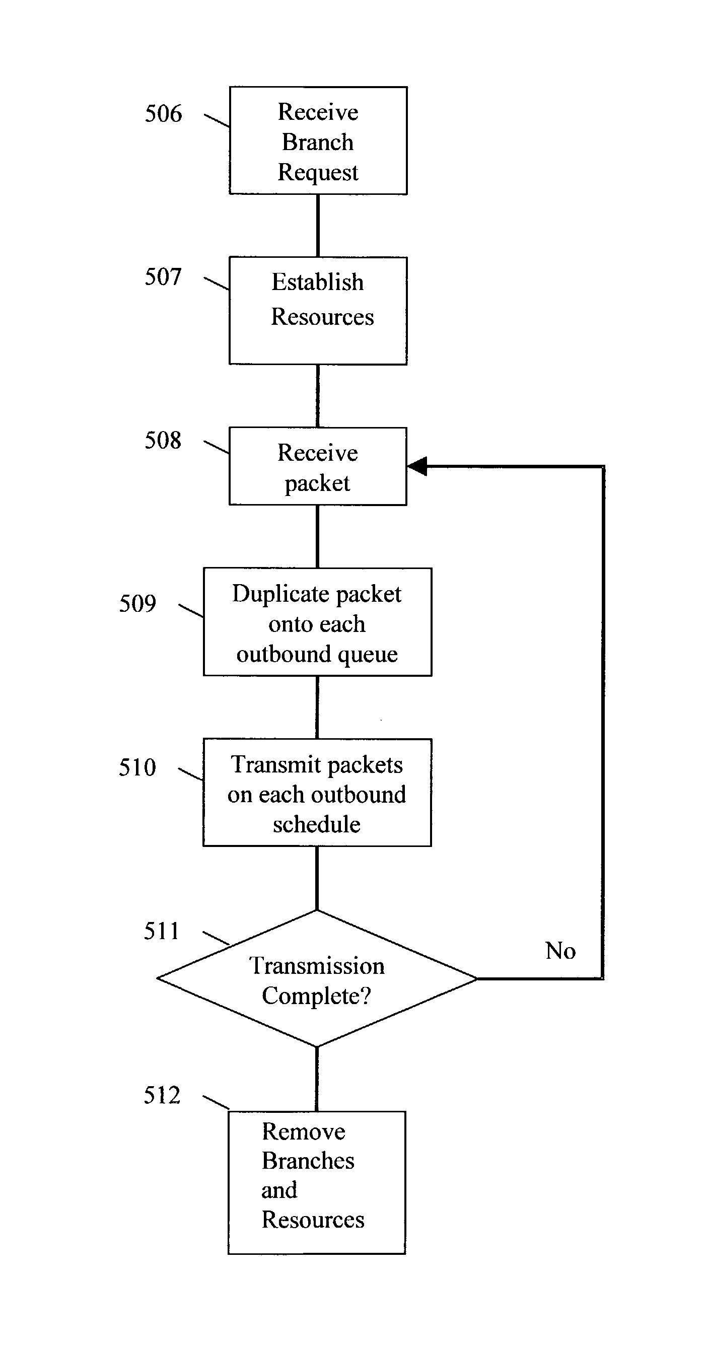
A receiver in such a system is burdened with the task of distinguishing valid data from erroneously duplicated data.
These solutions are error-prone at best, and can result in unstable transmissions while the system attempts to recover.
While such mechanism may provide the designer of such a system with a mechanism to sort and align data packets in sequence, the buffers add yet another set of problems such as excessive cost and added latency delays.
In addition, since the network systems do not perform the functions of phasing and sequence alignment, nor does it filter redundant packets, it is up to the end device to perform these functions, increasing processing and communications burdens on that device.
Multiple simultaneous surveillance targets and multiple LEAs are envisioned, further increasing complexity and generating further data traffic.
The interim standard recognizes that network congestion may result in loss of collected call data when store-and-forward resources are limited.
No known system presently has an efficient means for providing this specialized service.

Method used


Image

  • Generation of redundant scheduled network paths using a branch and merge technique
  • Generation of redundant scheduled network paths using a branch and merge technique
  • Generation of redundant scheduled network paths using a branch and merge technique

Examples


Embodiment Construction

[0061]As shown in FIG. 1, illustrating an embodiment of the present invention, end devices 300, 307 are connected to a packet network comprised of one or more packet switches A, B, C, D, known as scheduled switch / routers (SSRs). Each SSR comprises a functional implementation equivalent to that of a NETWORK SWITCH WITH PACKET SCHEDULING, as more fully described in the co-pending '744 application incorporated herein by reference. The packet network also includes a real-time schedule server 309, also called a Schedule Agent, which is configured to receive network connection requests from the end devices, establish a network itinerary for each required path through the network, and communicate scheduling information to the end devices and respective switches along each path. Other features of the Schedule Agent are described more fully in the co-pending '744 application incorporated by reference herein, in which the Schedule Agent is referred to as a “schedule server”, and the functiona...


PUM


Abstract

A method and apparatus for creating and using multiple redundant paths between endpoints in a scheduled communication network, and for sending copies of data down each path. A path calculation is made for one or more redundant paths between designated branch and merge points in a network using scheduled switch / routers, and duplicate packets are transmitted along each path to the merge point. The first packet received among the configured paths at the merge point is forwarded to a resulting data stream and the later (duplicate) copies from other paths are discarded. Path itineraries are configured to maintain temporal packet sequence in the resulting stream. Path status is monitored and additional paths can be substituted if a path has an outage. Alternatively, multiple divergent paths can be configured, and duplicate packets transmitted along each path, where at least one path delivers data between end points, and a monitoring path also transmits copies of the data to an alternate location. A new routing header may be attached to packets transmitted in the monitoring path, to facilitate conformance with CALEA monitoring requirements.

Description

CROSS REFERENCE TO RELATED APPLICATIONS[0001]This application is a continuation in part of U.S. patent application Ser. No. 09 / 746,744, entitled “NETWORK SWITCH WITH PACKET SCHEDULING,” filed on Dec. 22, 2000, which is incorporated by reference herein in its entirety (“the co-pending '744 application”). This application claims priority under 35 USC §119(e) to provisional application Ser. No. 60 / 344,448, entitled “GENERATION OF REDUNDANT SCHEDULED NETWORK PATHS USING A BRANCH AND MERGE TECHNIQUE,” filed on Nov. 1, 2001, which is hereby incorporated by reference herein in its entirety. The present application is also related to U.S. patent application Ser. No. 10 / 162,454, “REAL-TIME NETWORK SCHEDULED PACKET ROUTING SYSTEM”, filed 4 Jun. 2002, which is hereby incorporated by reference in its entirety (“the co-pending '454 application).FIELD OF THE INVENTION[0002]The present invention relates generally to fault tolerant data networking and specifically the implementation of a mechanism ...

Claims


Application Information

Patent Timeline
Patent Type & Authority Patents(United States)
IPC IPC(8): H04L12/28H04L12/26G01R31/08G06F11/00H04L12/56
CPCH04L12/5695H04L47/2416H04L47/781H04L47/801H04L47/822H04L47/829H04L47/70
Inventor ROGERS, STEVEN A.REITH, HOWARD C.WISLER, DALE J.
Owner AVAYA INC
Why Eureka
Try Eureka