Motion compensated image averaging

a technology of image averaging and motion compensation, applied in the field of image averaging, can solve the problems of difficult analysis of images using conventional techniques, low snr in gfap-gfp images of the mouse retina, and poor or satisfactory results

Inactive Publication Date: 2013-04-23
AGENCY FOR SCI TECH & RES
View PDF6 Cites 41 Cited by
  • Summary
  • Abstract
  • Description
  • Claims
  • Application Information

AI Technical Summary

Problems solved by technology

Conventional techniques for averaging image frames do not provide good or satisfactory results in some situations such as when the signal-to-noise ratio (SNR) is very low and the imaged object moves while the different image frames are taken.
However, the SNR in GFAP-GFP images of a mouse retina is typically very low and these images are difficult to analyze using conventional techniques.

Method used


Image

  • Motion compensated image averaging
  • Motion compensated image averaging
  • Motion compensated image averaging

Examples


examples

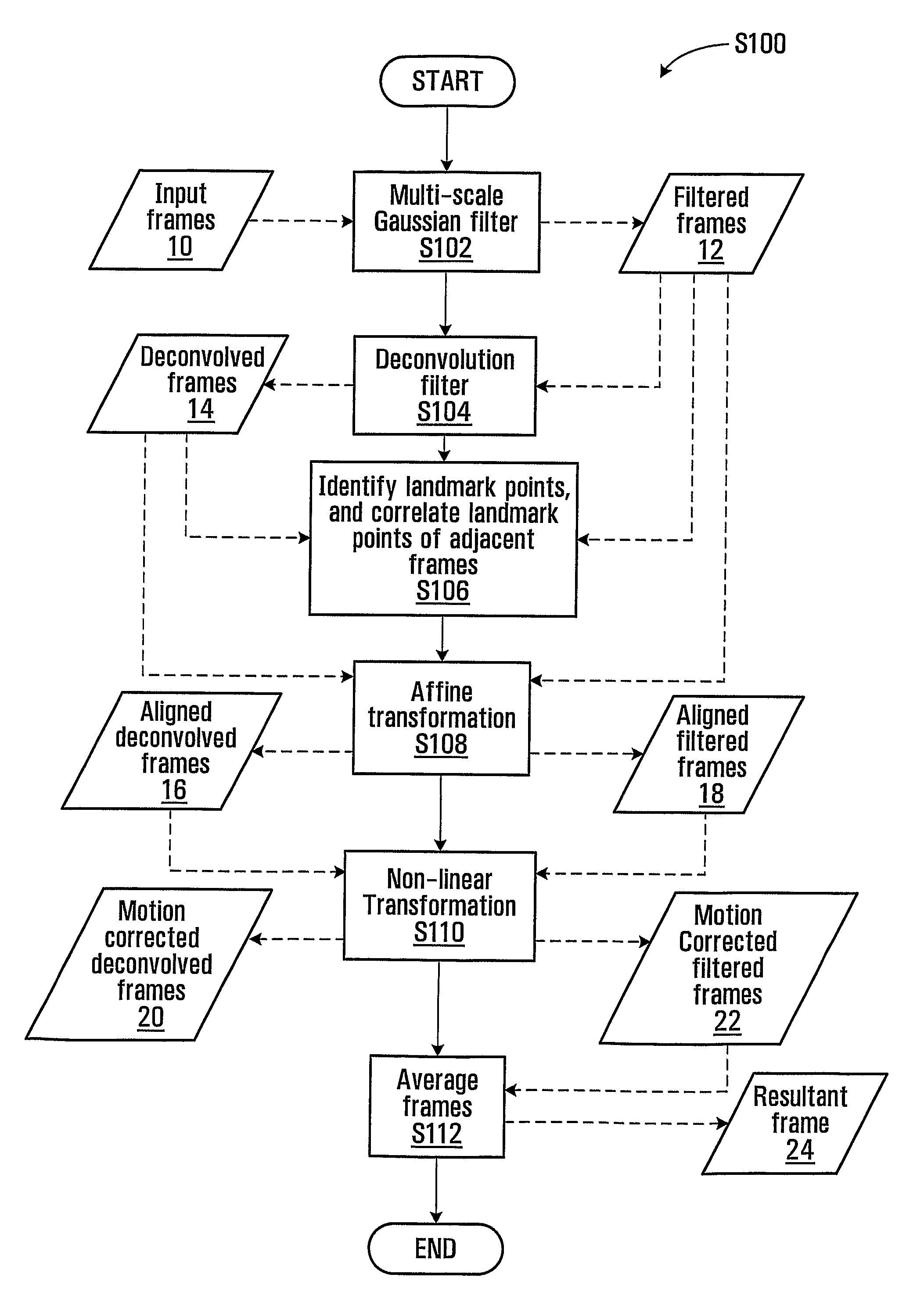
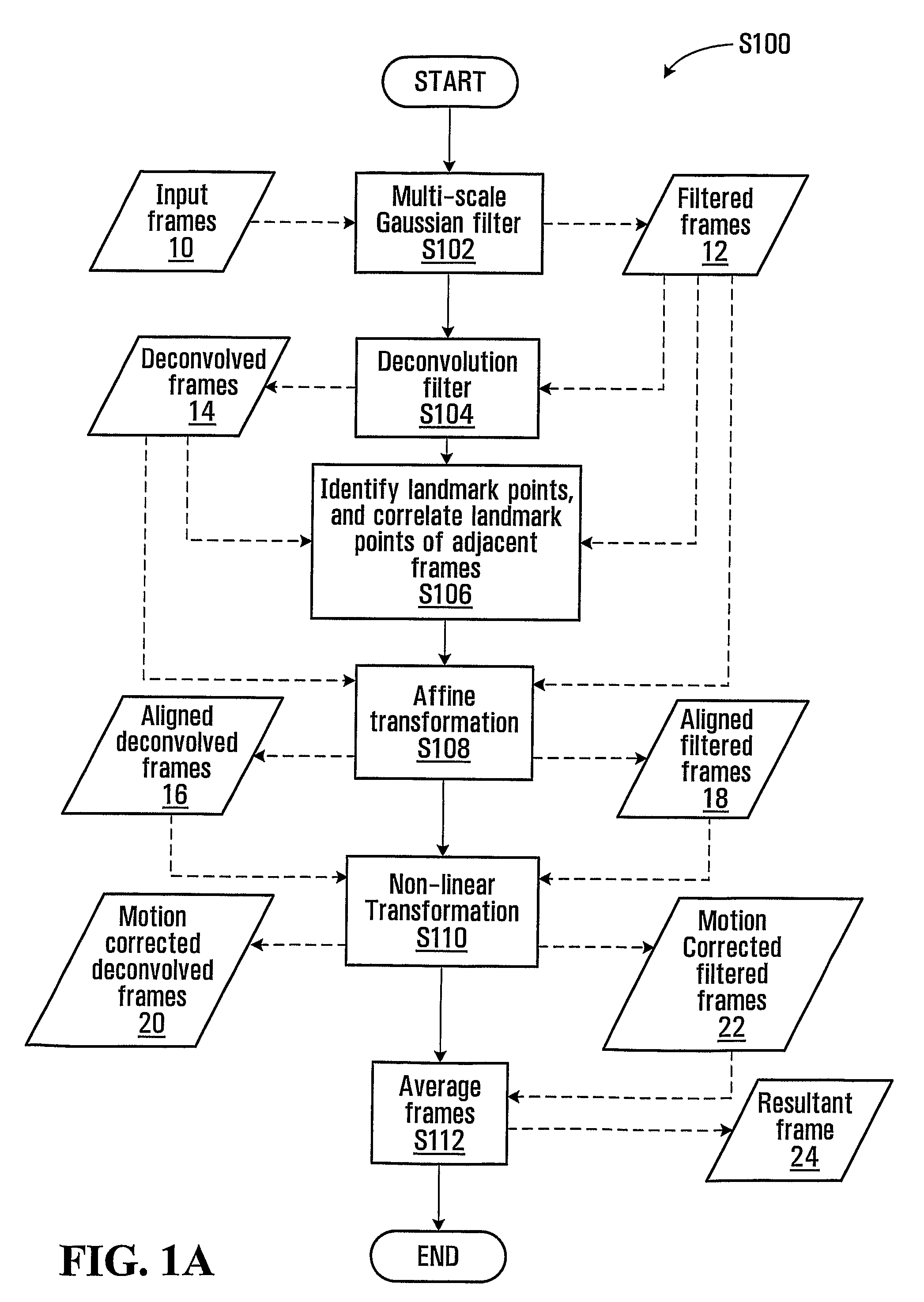
[0130]Example image frames were processed according to the process S100 using computer 200.

[0131]The processes used for processing these image frames included an algorithm which is illustrated with the following pseudocode:

[0132]

======================================%% Begin PseudocodeLoop from i =1 to N{execute subprocess S102 to generate filtered frame Ifi from rawframe Iiexecute subprocess S104 to generate deconvolved frame Ji fromfilteredframe Iiexecute subprocess S160 to identify landmark points in JiIf i > 1{execute S162 to correlate landmark points in Ji and Ji−1execute S108 to align Ifi with Iai−1, generating aligned frame Iaiexecute S110 to correct alignment of Iai to Irefi−1, generatingcorrectedframe Ini and reference frame IirefIA = [(i−1)*IA + Ini] / iELSEIA = Ifi} end if i >1} end loop from i = 1 to N%% End Pseudocode=========================================

example i

[0133]A sample raw frame of a GFAP-GFP image of a mouse retina taken in vivo and processed in this Example is shown in FIG. 3A.

[0134]FIG. 3B shows a deconvolved frame generated from a filtered frame which is in turn generated from the raw frame of FIG. 3A, after the application of a multi-scale Gaussian filter and a deconvolution filter. As can be seen, the underlying features in the image were enhanced without significant distortion in FIG. 3B. This result indicates that, in this case, subjecting the filtered frame to deconvolution facilitates accurate estimation of the underlying fluorescence signal in the filtered frame.

[0135]FIG. 3C shows a comparison frame generated from the filtered frame of FIG. 3B by applying a 9×9 median filter only. The underlying signal was less enhanced as compared toFIG. 3B. Some image artifacts were visible in FIG. 3C, but were absent in FIG. 3B.

[0136]FIG. 3D shows a comparison frame which was generated by simple averaging.

[0137]FIGS. 4A, 4B, 4C, and 4...

example ii

[0138]Raw image frames were obtained from the retina of two different mice having the FVB / N strain, using a Heidelberg Retina Angiograph (HRA2) system. A blue laser (488 nm) was used to excite the transgenic GFAP-GFP expression and the barrier filter was set at 500 nm. The field of view was originally set to 30° but the images displayed here are of a more localized region around the optic nerve head since this is the region of interest. All retinal images have a transverse resolution of 10 um. The raw retinal images were acquired over two weeks at specific time points (different days). At the onset of the experiment, immediately after retinal imaging on day zero, the control mice was injected with saline and the treated mice was injected with kainic acid, intraperitoneally. A sequence of raw images were taken each day and were averaged according to the process S100 as further detailed in the Example above to obtain a resultant image for that day. The parameters used for the averagin...


PUM


Abstract

A method is provided for averaging a sequence of image frames. A noise-reducing filter is applied to the image frames to generate filtered frames. A deconvolution filter is applied to the filtered frames to generate corresponding deconvolved frames. The filtered frames are transformed by an affine transformation to align them, generating aligned frames. The aligned frames are motion corrected by non-linear transformation based on intensity rank matching, generating a sequence of motion-corrected frames. The motion-corrected frames are averaged to generate a resultant frame.

Description

CROSS-REFERENCE TO RELATED APPLICATION[0001]This application claims the benefits of U.S. provisional application No. 60 / 924,162, filed May 2, 2007, the contents of which are incorporated herein by reference.FIELD OF THE INVENTION[0002]The present invention relates to image averaging, particularly to averaging a sequence of image frames that require noise filtering and motional correction.BACKGROUND OF THE INVENTION[0003]It is often necessary or desirable to average multiple images taken from a same object to obtain an averaged image with improve quality, such as with reduced noise. Conventional techniques for averaging image frames do not provide good or satisfactory results in some situations such as when the signal-to-noise ratio (SNR) is very low and the imaged object moves while the different image frames are taken. For example, in vivo fluorescent images of a mouse retina can be obtained based on a technique using the green fluorescence protein (GFP) transgenic mouse model with...

Claims


Application Information

Patent Timeline
Patent Type & Authority Patents(United States)
IPC IPC(8): G06K9/00G06K9/64G06K9/40
CPCG06T5/50G06T5/002G06T5/003G06T5/20G06T2207/10016G06T2207/10064G06T2207/20016G06T2207/20036G06T2207/30004
Inventor ZHUO, LANGKUMAR, SARAVANAHO, GIDEON
Owner AGENCY FOR SCI TECH & RES
Why Eureka
Try Eureka