Stashing system and method for the prevention of cache thrashing

Active Publication Date: 2013-04-23
AMPERE COMPUTING LLC
View PDF17 Cites 18 Cited by
  • Summary
  • Abstract
  • Description
  • Claims
  • Application Information

AI Technical Summary

Benefits of technology

[0009]Disclosed herein are a queue manager based system and method for using cache stashing to efficient process packets. The disclosed system removes the l

Problems solved by technology

A major problem in packet processing involves the latency in reading packets stored in an external system memory, such as a double data rate (DDR) memory, for further processing by a central processing unit (CPU) or processor.
Generally, access to system memory is expensive and the latency is in terms of hundreds of nanoseconds.
This memory read process is performed for every packet, and it introduces significant delay in packet processing.
However, if the packet incoming rate increases faster than the pac

Method used


Image

  • Stashing system and method for the prevention of cache thrashing
  • Stashing system and method for the prevention of cache thrashing
  • Stashing system and method for the prevention of cache thrashing

Examples


Embodiment Construction

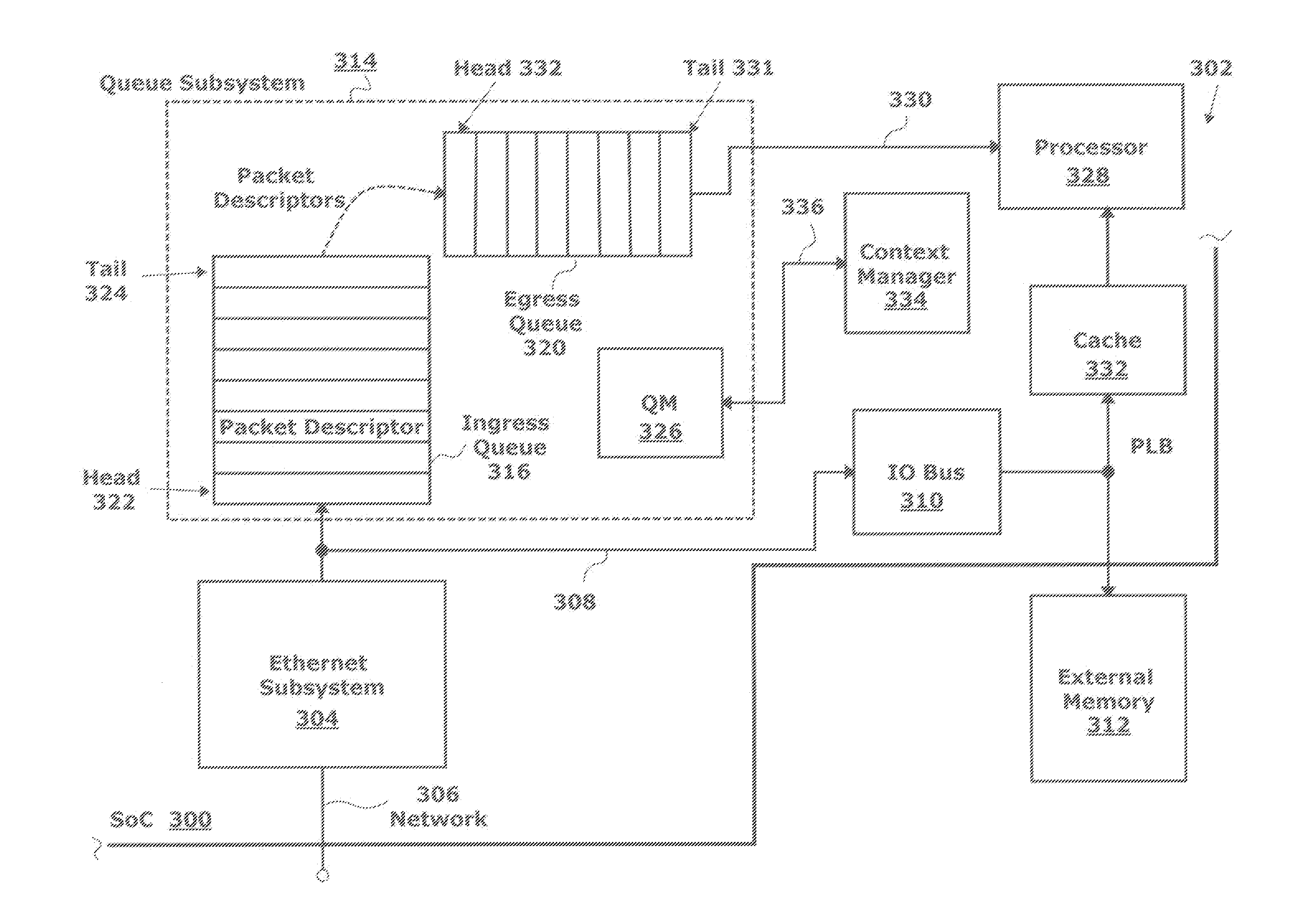
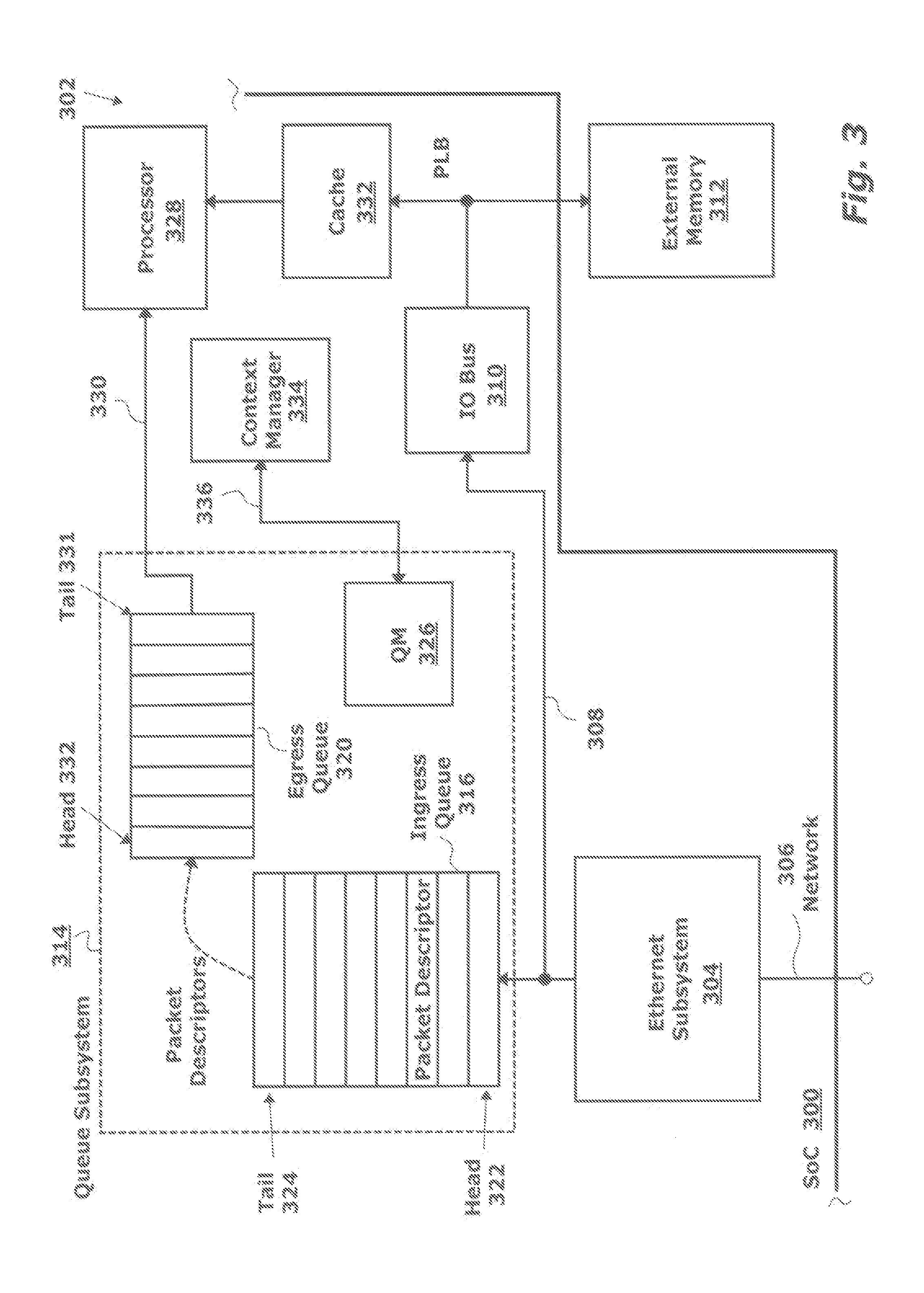
[0018]FIG. 3 is a schematic block diagram of a system-on-chip (SoC) 300 including a processor, with a system for stashing packet information that prevents cache thrashing. The system 302 comprises an Ethernet subsystem 304 having a network interface on line 306 for accepting a plurality of packets. The Ethernet subsystem 304 derives a packet descriptor for each accepted packet. The Ethernet subsystem 304 has an interface on line 308 connected to an input / output (IO) bus 310 to supply the packet descriptors and to supply the packets to an external memory 312. Typically, the external memory 312 is located off-SoC as shown, but alternatively the memory may be embedded in the SoC. A queue subsystem 314 includes an ingress queue 316 with a head 318 connected to the IO bus 310. An egress queue 320 has a head 322 connected the tail 324 of the ingress queue 316. A queue manager (QM) 326 adds each packet descriptor to the ingress queue 316 and transfers the packet descriptors from the ingres...


PUM


Abstract

In a system-on-chip (SoC) including a processor, a method is provided for stashing packet information that prevents cache thrashing. In operation, an Ethernet subsystem accepts a plurality of packets and sends the packets to an external memory for storage. A packet descriptor is derived for each accepted packet and is added to an ingress queue. Packet descriptors are transferred from the ingress queue to an egress queue supplying the packet descriptors to a processor. A context manager monitors the fill level of packet descriptors in the egress queue. In response to monitoring the fill level, the context manager stashes packets from the external memory into a cache, where each stashed packet is associated with a packet descriptor in the egress queue. Packet descriptors are transferred from the ingress queue to the egress queue in response to a number of packet descriptors in the egress queue falling below the fill level.

Description

BACKGROUND OF THE INVENTION[0001]1. Field of the Invention[0002]This invention generally relates to computer processing and, more particularly, to a system and method for packet processing that prevents the occurrence of cache thrashing.[0003]2. Description of the Related Art[0004]FIG. 1 is a schematic diagram depicting the flow of processing in a conventional packet system (prior art). A major problem in packet processing involves the latency in reading packets stored in an external system memory, such as a double data rate (DDR) memory, for further processing by a central processing unit (CPU) or processor. For incoming packets, the CPU generally allocates a buffer descriptor ring. When packet P1 arrives on the input / output (IO) interface, this packet is copied to system memory and packet-related information such as packet address, packet length, and other information are copied into packet descriptor 1. Then, the IO triggers an interrupt to the CPU. The CPU reads buffer descripto...

Claims


Application Information

Patent Timeline
IPC IPC(8): G06F3/00G06F13/14
CPCG06F3/00G06F13/14H04L47/50H04L12/40143H04L12/413H04L49/351H04L49/102H04L49/90H04L49/109
Inventor CHUDGAR, KEYURSATHE, SATISH
Owner AMPERE COMPUTING LLC
Why Eureka
Try Eureka