Method and device for operating a combustion engine

a combustion engine and combustion engine technology, applied in the direction of electrical control, process and machine control, instruments, etc., can solve the problems of only being able to achieve the desired combustion, the speed with which the controller can be applied, and the risk of an unwanted operating state of the combustion engin

Active Publication Date: 2013-05-07
ROBERT BOSCH GMBH
View PDF34 Cites 12 Cited by
  • Summary
  • Abstract
  • Description
  • Claims
  • Application Information

AI Technical Summary

Benefits of technology

[0016]One idea of the above method is to generate the manipulated variable for setting the combustion in the cylinders as a function of combustion information about a quality of the combustion, in doing which, it is possible in particular to avoid negative consequences of an EGR-rate deviating too sharply upward or downward from an optimal EGR-rate, by taking the combustion information into consideration. Alternatively, the combustion information, such as the deviation from the optimal EGR-rate or, in general, the deviation from the desired air-system state, may also be obtained indirectly via information from the air-system control.
[0018]Consequently, it is possible to adapt the combustion feature to the state of the air system in the dynamics, thus making it possible to prevent the combustion from taking place with too high a noise generation, or possibly misfiring.
[0036]According to one specific embodiment, a dynamics-recognition block is provided which indicates when the combustion engine is in a dynamic operating state; when the dynamic operation ends, correction value CV is taken back in such a way that there are no sudden changes in the manipulated variable for setting the combustion in the cylinders of the combustion engine.

Problems solved by technology

Since, in principle, such a control is only able to react after the control deviation has occurred, and the speed with which the controller can be applied must be limited for reasons of stability, the setting to the desired combustion is only possible with a delay which, according to experience, corresponds to several working cycles of the combustion engine.
Because of the high EGR rates used in the new diesel combustion systems, the combustion engine is operated closer to a stability limit, so that in response to an EGR-rate deviating slightly from the setpoint EGR-rate set, the risk of an unwanted operating state of the combustion engine develops.
The exceeding of the optimal EGR-rate leads, in particular, to an increased risk of misfirings, and if there is a drop below the optimal EGR-rate, the noise generation during the combustion increases unacceptably.
Especially during dynamic operation with respect to the speed and the load of the combustion engine, in which, because of the sluggishness of the air system, it is inherent in the system that the necessary EGR-rate is exceeded or not attained, this represents a challenge for the engine management.
Because of the delay described above, the conventional control of the air system is not able to continuously retain the relevant air-system variables, such as the EGR-rate, at the optimal value.
Therefore, the dynamic operation of the combustion engine may be associated in particular either with too high a noise generation or with an increase in the risk of combustion misfirings.
Since, for stability reasons, the speeds with which the controls can be applied must be limited, in the case of longer deviations between setpoint and actual values, a not inconsiderable integration component may build up which may lead to misfirings in the event of rapid changes in the operating point and a rapid commencement of the exhaust-gas recirculation as a result.

Method used


Image

  • Method and device for operating a combustion engine
  • Method and device for operating a combustion engine
  • Method and device for operating a combustion engine

Examples


Embodiment Construction

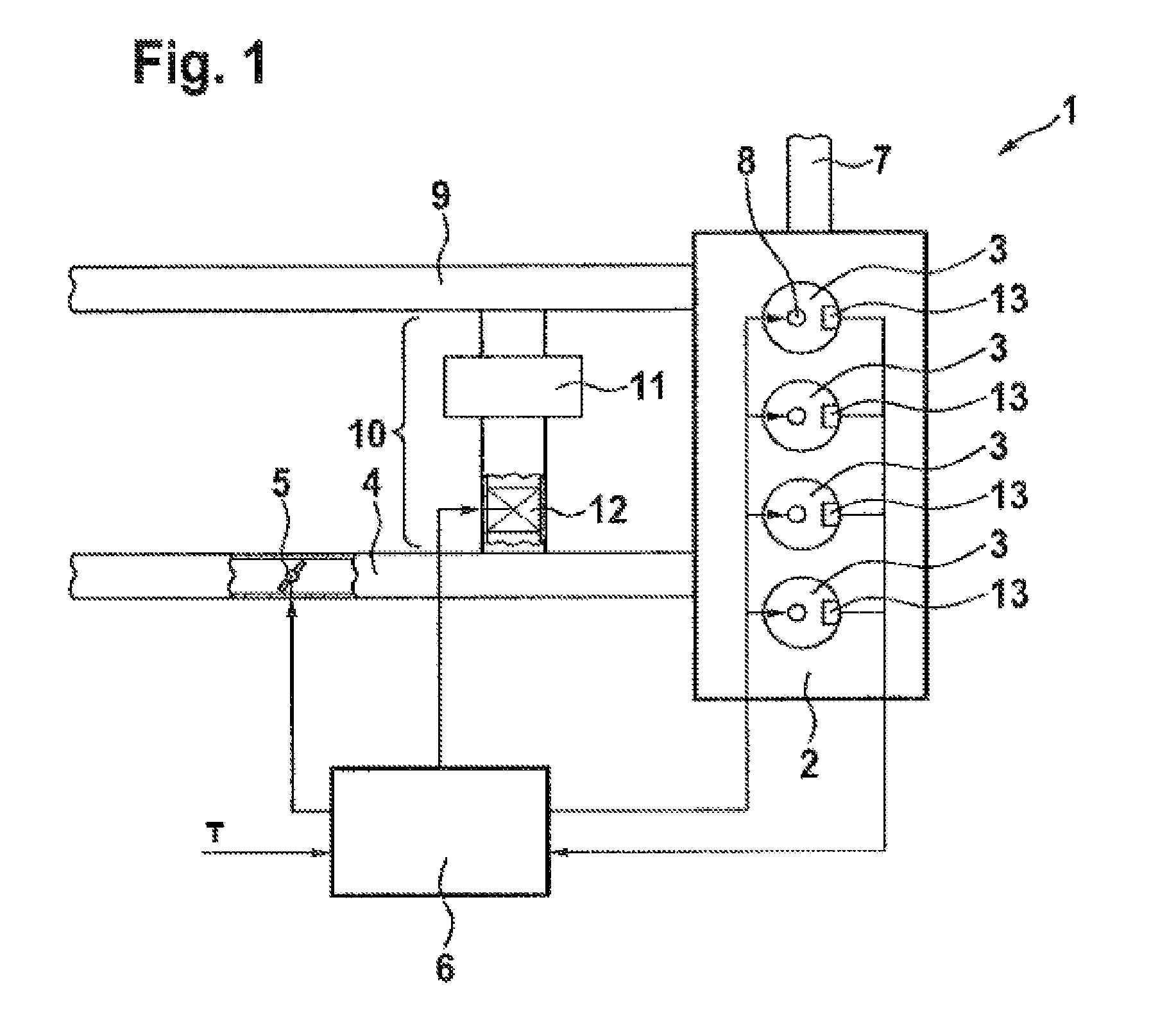
[0045]FIG. 1 shows an engine system 1 having an auto-ignition combustion engine 2 such as a diesel engine, including one or more (in the case shown, four) cylinders 3. Air or an air / exhaust-gas mixture is supplied to cylinders 3 via an air-feed section 4 and via corresponding intake valves (not shown). Disposed in air-feed section 4 is a throttle valve 5 which may be adjusted by an engine-control unit 6 to control the air feed into combustion engine 2. Moreover, fuel is injected via a fuel feed 7 into cylinders 3 by way of corresponding fuel injectors 8. The point of injection and the injection period, which corresponds essentially to the quantity of fuel injected into corresponding cylinder 3, are predefined by engine-control unit 6 as a function of operating states of combustion engine 2 and of external torque demands T such as a torque required by the driver.

[0046]Combustion exhaust gases are exhausted out of cylinders 3 via corresponding exhaust valves (not shown) and carried aw...


PUM


Abstract

A method for setting a combustion in a combustion engine, particularly in a diesel engine, having the following steps of generating a manipulated variable, particularly a point of injection (PI), as a function of a combustion feature (MFB50%), the combustion feature (MFB50%) representing a condition in cylinder, especially a pressure characteristic in the cylinder, and setting the combustion in cylinders of the combustion engine with the aid of the manipulated variable, the manipulated variable further being generated as a function of a correction value (CV), which is determined as a function of combustion information (dQmax) that provides an indication about the quality of the combustion.

Description

FIELD OF THE INVENTION[0001]The present invention relates to auto-ignition combustion engines, particularly a method and a device for operating diesel engines, especially for determining a point of injection for diesel engines.BACKGROUND INFORMATION[0002]To operate an auto-ignition combustion engine such as a diesel engine, for instance, a combustion-position control is carried out for new combustion processes, by which the points of injection of fuel into the cylinders are set. Such a control is based on pressure features ascertained in the combustion chamber, such as data about a combustion position or the indicated work, in particular, based on the combustion feature MFB50% (mass fraction burned) (MFBx %: crankshaft angle at which x % of the fuel injected in the cylinder is burned).[0003]With the control of the combustion position, the combustion in the cylinders is suitably corrected as a function of the control deviation by at least an intervention with respect to the point of ...

Claims


Application Information

Patent Timeline
Patent Type & Authority Patents(United States)
IPC IPC(8): F02M7/00F02B5/00
CPCF02D35/023F02D35/028F02D41/401Y02T10/40
Inventor FISCHER, WOLFGANGSEULING, SILKE
Owner ROBERT BOSCH GMBH
Why Eureka
Try Eureka