Sealed cleaner-box with magnetically coupled actuator pucks

a cleaner box and actuator technology, applied in the field of sealed cleaner boxes, can solve the problems of inefficiency of closed automatic spray operations, inconvenient cleaning, and contaminated fluids, and achieve the effects of minimizing friction, reducing scratching, and reducing friction

Inactive Publication Date: 2013-05-07
TRANSITION AUTOMATION
View PDF13 Cites 0 Cited by
  • Summary
  • Abstract
  • Description
  • Claims
  • Application Information

AI Technical Summary

Benefits of technology

[0008]An object of the present invention is to provide a sealed cleaning enclosure where two magnetically coupled pucks are positioned flush with the transparent window of the enclosure, one on the outside, and one on the inside. In the present embodiment, the inside puck is configured to spray a cleaning fluid, or to blast compressed air at the objects to be cleaned. In other configurations, the system could have a cleaning fluid puck, an air blast puck and a rinse fluid puck. The term “puck” is used, because both the outside puck and the inside puck are fitted with ball bearings which allow each puck to roll with very little friction on the surface of the transparent windows. This minimizes friction and also scratching which might occur if the pucks were simply sliding on the surface of the transparent windows. The system of the present invention also includes a light to highlight and illuminate the area being cleaned. Each liquid may be contained in its own separate feed tank also called a “trap”. Also, all liquid and air blast functions could be consolidated into one “puck” inside the cleaner box, or could be handled by three separate pucks which could be alternatively parked and / or coupled with the outside actuator puck.

Problems solved by technology

Many systems used for cleaning contain solvents such as alcohol, or other cleaning agents and these fluids often become contaminated with the materials they are used to clean such as solder paste.
Most such cleaning systems involve closed automatic spray operations that are inefficient because they apply aggressive cleaning action to entire areas even if the objects to be cleaned are only small, or if the areas to be cleaned are confined to a small area.
Other systems involve placing objects in tanks with open covers, which enable operators to spray and view the contaminated objects, however, because these systems are generally vertical tanks to contain the cleaning fluid and draining fluid, the visibility is limited by looking down vertically.
This does not offer an desirable arrangement for operators, because the tanks are large and the operators often have to stand on step stools and look into the tank.
While these systems offer more efficiency by allowing spot cleaning, they are still not optimal.

Method used


Image

  • Sealed cleaner-box with magnetically coupled actuator pucks
  • Sealed cleaner-box with magnetically coupled actuator pucks
  • Sealed cleaner-box with magnetically coupled actuator pucks

Examples


Embodiment Construction

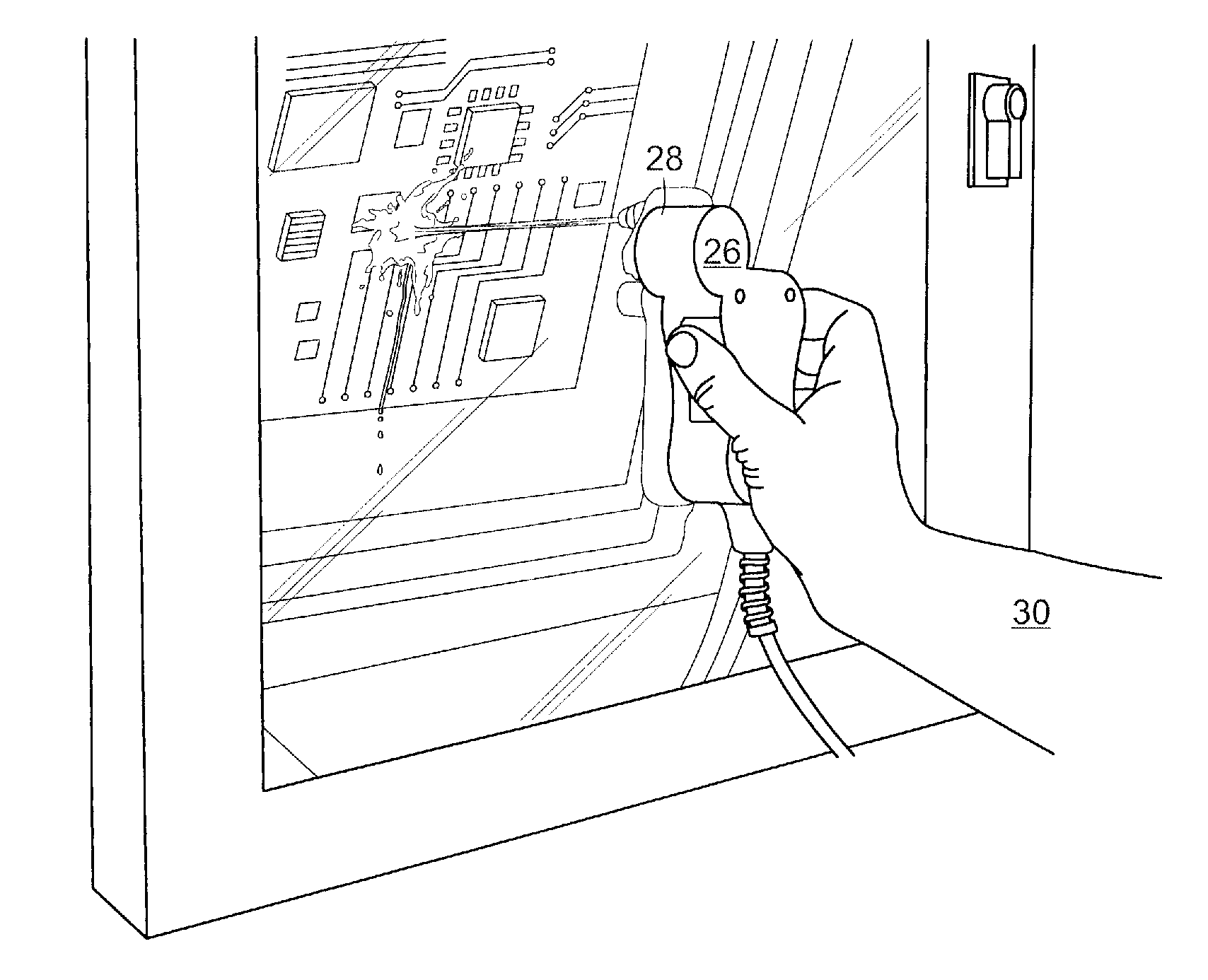
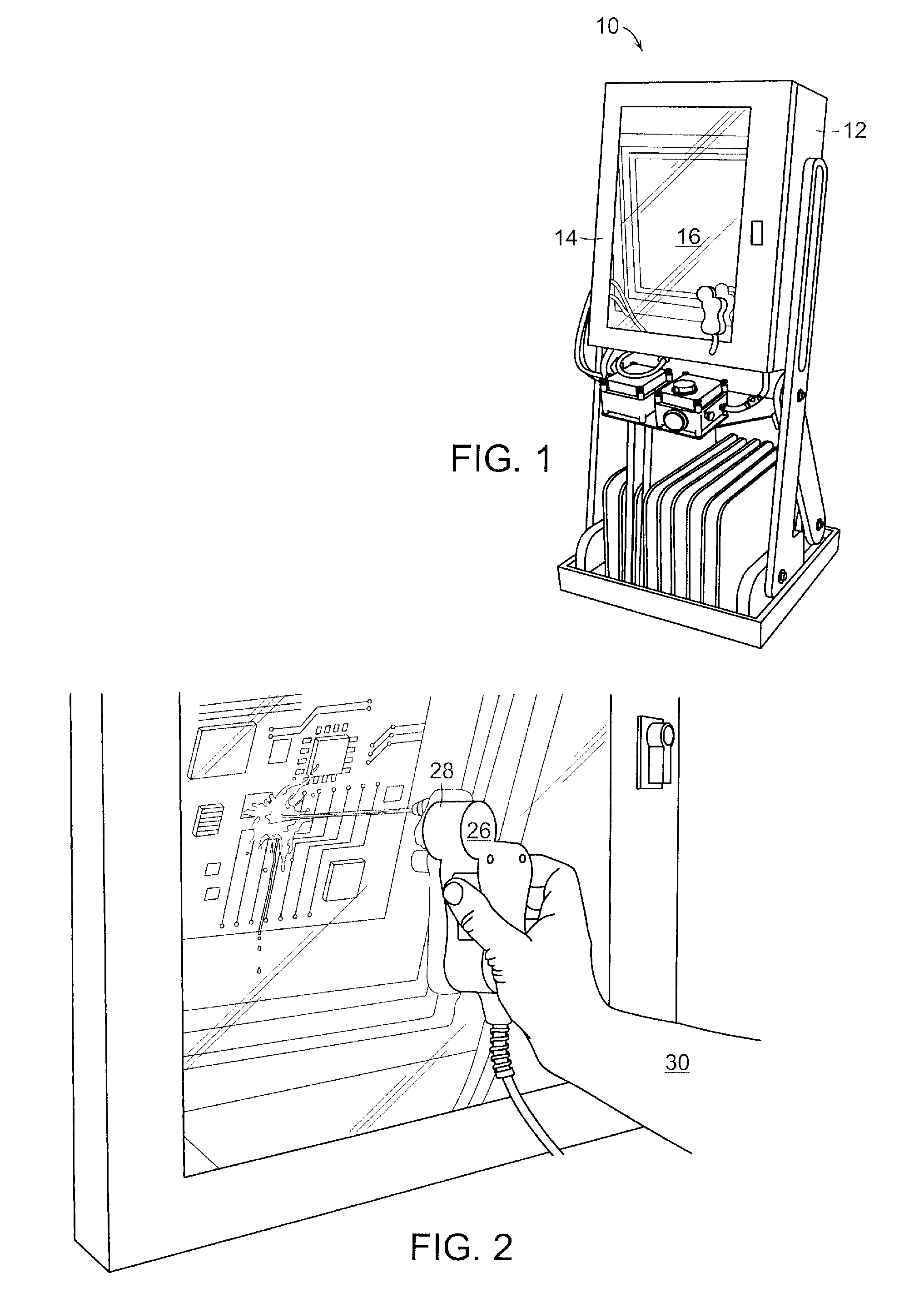
[0019]This apparatus was developed as a way to remove solder paste from squeegee blades and stencils but may also be useful for other industries such as cleaning surgical tools in the medical field or removing pesticides in the food processing industry. The invention has a specific function of segregation which has valuable utility in any manufacturing or mining activity where materials need to be separated, and any of the components or materials are valuable (need to be recycled) or are hazardous (need to be contained and separated from humans).

[0020]For example, it is common to use both silver loaded epoxies in the manufacturing of solar cells, and often, the stencils or misprinted substrates need to be cleaned. It is important to collect the residual silver loaded epoxy to recycle the silver that is collected. The present invention offers a closed system that allows for the entrapment and collection of the valuable silver. The equipment offers a unique way to clean soiled or cont...


PUM


Abstract

A cleaning system which includes an enclosure and having a door with a transparent window. The door is opened and closed to load and unload products to be cleaned. An operator puck on the outside of the enclosure couples magnetically to another actuator puck on the inside of the enclosure. This coupling allows an operator to move and direct the inside puck to actuate spray or air blast functions, without opening the enclosure. The outside operator puck includes one or more switches which turn on the various electronic components such as the liquid pump, light, or air blast valve. The cleaning system enables a user to efficiently direct cleaning action to parts inside to minimize the cleaning time, and to prevent exposure of chemicals. The cleaning fluid is cycled out of the enclosure continuously, and into a “trap” box, through a pump and back into the cleaner box in a closed loop cycle. This system reduces exposure of users to cleaning chemicals and their vapors prevent the chemicals from being deposited into the environment.

Description

PRIORITY INFORMATION[0001]This application claims the benefit of U.S. Patent Application Ser. No. 61 / 165,201 filed on Mar. 31, 2009, all of which is incorporated herein in its entirety.BACKGROUND OF THE INVENTION[0002]1. Field of the Invention[0003]The invention relates to the field of cleaning systems, and in particular to a system comprised of a sealed enclosure having a transparent door such that a pair of magnetically coupled pucks enables an operator to move and direct a flow of cleaning fluid to clean objects located within the enclosure.[0004]2. Description of the Prior Art[0005]There is an increasing concern with regard to the effects of hazardous materials on the environment. So one needs to be concerned any time potentially hazardous materials are being used in any process. That includes materials which may be hazardous to humans or other animals or to the environment.[0006]There is a trend and value in current manufacturing operations to remove any chemical exposure and l...

Claims


Application Information

Patent Timeline
Patent Type & Authority Patents(United States)
IPC IPC(8): B08B3/02
CPCB08B3/006
Inventor CURTIN, MARK
Owner TRANSITION AUTOMATION
Why Eureka
Try Eureka