
Power switchgear

a switchgear and power technology, applied in the direction of substations, electrical apparatus casings/cabinets/drawers, instruments, etc., can solve the problems of affecting the thermal conditions of the switchgear, the inability to directly place the busbars, and the inability to design the switchgear. to achieve the effect of convenient disassembly and assembly, efficient evacuation and large elasticity

Active Publication Date: 2013-05-07
ABB (SCHWEIZ) AG
View PDF15 Cites 23 Cited by
  • Summary
  • Abstract
  • Description
  • Claims
  • Application Information

AI Technical Summary

Benefits of technology

The invention allows for the placement of insulating radiators anywhere on the current path elements, which helps to improve heat exchange and evacuation of heat from adjacent elements. The use of thermoplastic materials makes the installation of radiators easier and more cost-effective compared to metal radiators. The use of snap-fit elastic catches allows for quick assembly and disassembly of radiators without the need for additional elements like screws.

Problems solved by technology

In high voltage equipment, due to high currents, overheating of elements of the current path takes place, which adversely affects the thermal conditions in the switchgear.
Indirectly, this allows also to reduce the temperature of the current path elements, but the efficiency of such design is limited.
However, due to the fact that radiators are made of electrically conductive materials, such as aluminium or copper, they cannot be placed directly on the busbars.
Their presence will result in the reduction of insulation gaps in the switchgear and will cause disturbance and unfavourable distribution of the electric field, which may lead to short circuits and destruction of the switchgear.

Method used


Image

  • Power switchgear
  • Power switchgear
  • Power switchgear

Examples


Embodiment Construction

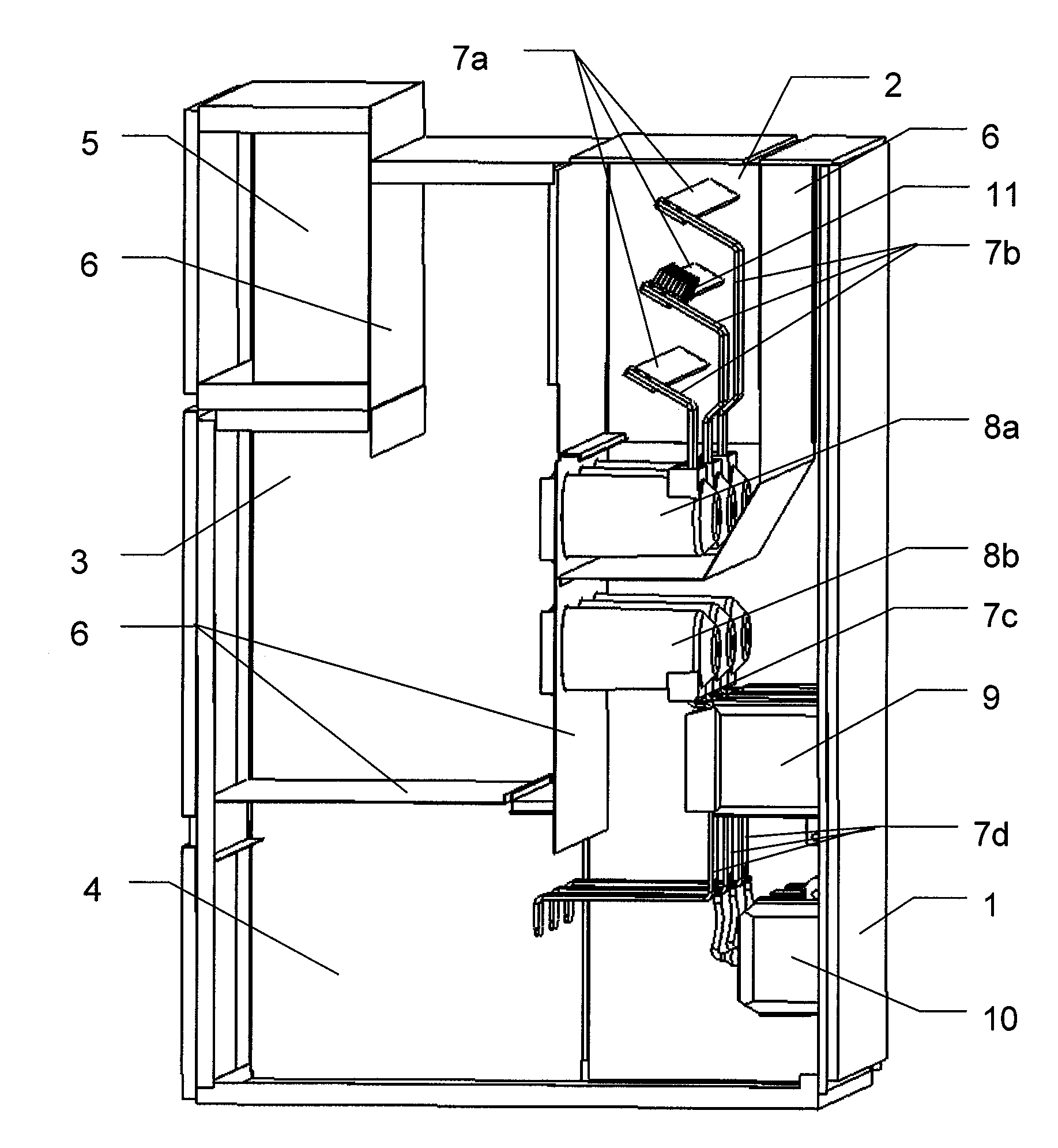
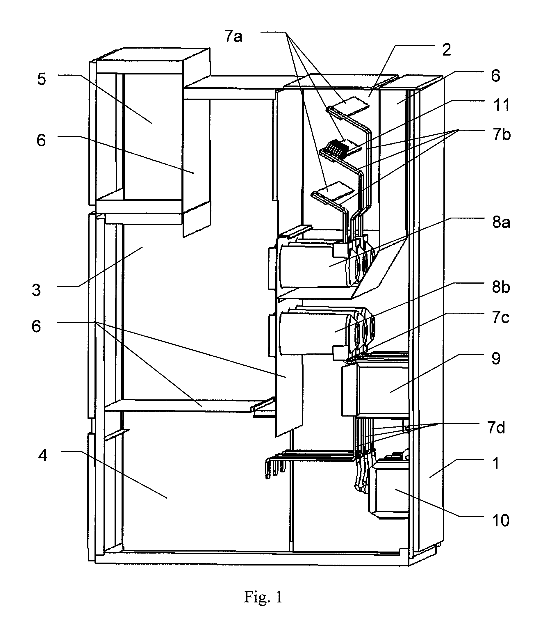
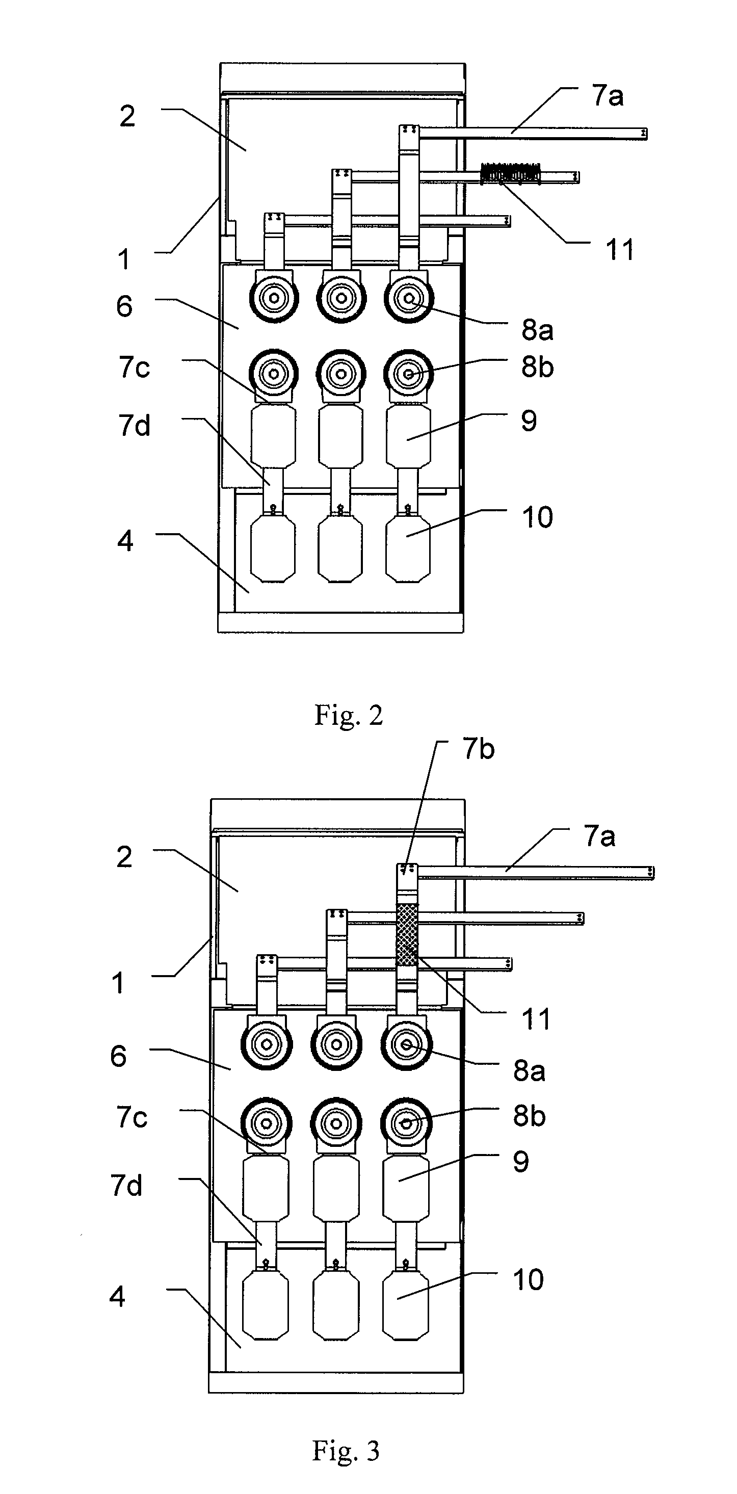
[0031]The switchgear whose diagram is shown in FIG. 1 has a steel casing 1 comprising four main compartments: a busbar compartment 2, a circuit-breaker compartment 3, a feeder compartment 4, and a low voltage compartment 5. Individual compartments are divided from one another by steel segregation walls 6. In the busbar compartment 2, busbars 7a are connected on one end with the output of a circuit breaker, not shown in the drawing, which is placed in the circuit-breaker compartment 3, through branches 7b and resin components so called “busbar side chambers”8a, while their other end is a connection with the analogous busbar compartment of the neighbouring switchgear cabinet, not shown in the drawing. In the feeder compartment 4 the circuit breaker from the circuit-breaker compartment 3, through so called “cable side chambers”8b, branches 7c and 7d is connected with current transformers 9, voltage transformers 10 and cable connections not shown in the drawing. Insulating radiator 11 i...


PUM

PropertyMeasurementUnit
Thicknessaaaaaaaaaa
Shapeaaaaaaaaaa
Electrical conductoraaaaaaaaaa

Abstract

The subject of the invention is an electric power switchgear, an insulating radiator, and a method for installing the radiator in an electric power switchgear, and in particular in a medium or high voltage switchgear. The electric power switchgear comprising working elements placed in the housing and connected with busbars and branches, and cooled with air, is characterized in that it contains at least one insulating radiator made of thermoplastic material of increased thermal conductivity λ≧2 W / mK, which is placed in the electric field of the switchgear and which is connected by a non-permanent fastening to at least one busbar or / and at least one branch. The insulating radiator designed for the switchgear is an injection molding including a base plate to whose top face a system of heat evacuating elements of identical or diverse shape is attached, and to its side surfaces elastic assembly catches are fixed.

Description

CROSS-REFERENCE TO RELATED APPLICATION[0001]This is a §371 application of International patent application number PCT / EP2010 / 004402 filed Jul. 8, 2010, which claims priority of European patent application number 09460033.5 filed Jul. 27, 2009, both of which are incorporated herein by reference.TECHNICAL FIELD[0002]The subject of the invention is a power switchgear, an insulating radiator, and a method of fitting the radiator in the power switchgear, and especially in a medium or high voltage switchgear.BACKGROUND ART[0003]In high voltage equipment, due to high currents, overheating of elements of the current path takes place, which adversely affects the thermal conditions in the switchgear. In order to improve heat evacuation from inside the switchgear and lower the temperature, a special window is made in its casing to force air circulation to provide the ventilation of the switchgear.[0004]A method and a device for separating cooling air in the switchgear cubicle are known from pa...

Claims


Application Information

Patent Timeline
IPC IPC(8): H05K7/20H05K13/00H02B5/00H02B1/56
CPCH02B1/56H02B11/04H02G5/10H02B13/025Y10T29/49002
Inventor KASZA, KRZYSZTOFMALINOWSKI, LUKASZSEKULA, ROBERT
Owner ABB (SCHWEIZ) AG
Learn More