Security apparatus

a technology of security apparatus and cassettes, which is applied in the field of security systems and apparatuses, can solve the problems of high risk of theft of all of the cash stored in the cassettes, the inaccessibility of all cassettes and the cash they contain, and the inability to store all of the cash in the cassettes. it is easy to be stolen and other problems, to achieve the effect of reducing the risk of th

Inactive Publication Date: 2013-05-14
SCOTIA SAFES
View PDF25 Cites 6 Cited by
  • Summary
  • Abstract
  • Description
  • Claims
  • Application Information

AI Technical Summary

Benefits of technology

[0007]It is the objective of the present invention to a

Problems solved by technology

One major security weak point still exists in many ATMs.
That is, all of the cash stored within the cassettes is at high risk from theft when the housing door of an ATM is opened to replenish the cash or to allow servicing or maintenance to be performed.
However, when the locking bar is removed to allow access to one of the cassettes for refilling or replacing, all of the cassettes and the cash they contain become accessible and vulnerable to theft.
However, this arrangement has drawb

Method used


Image

  • Security apparatus
  • Security apparatus
  • Security apparatus

Examples


Embodiment Construction

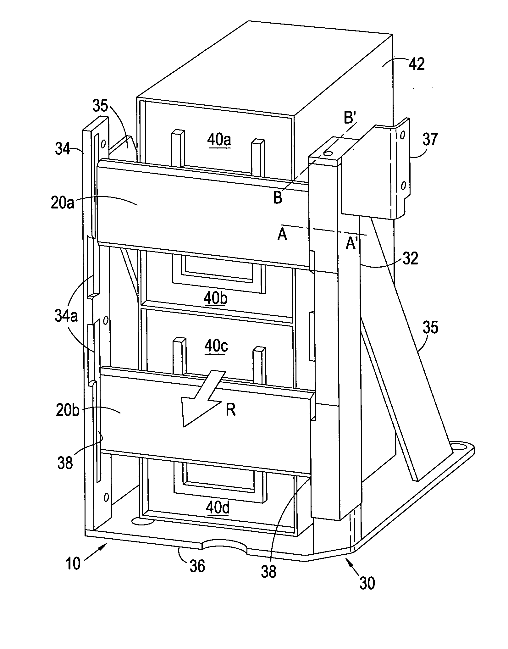
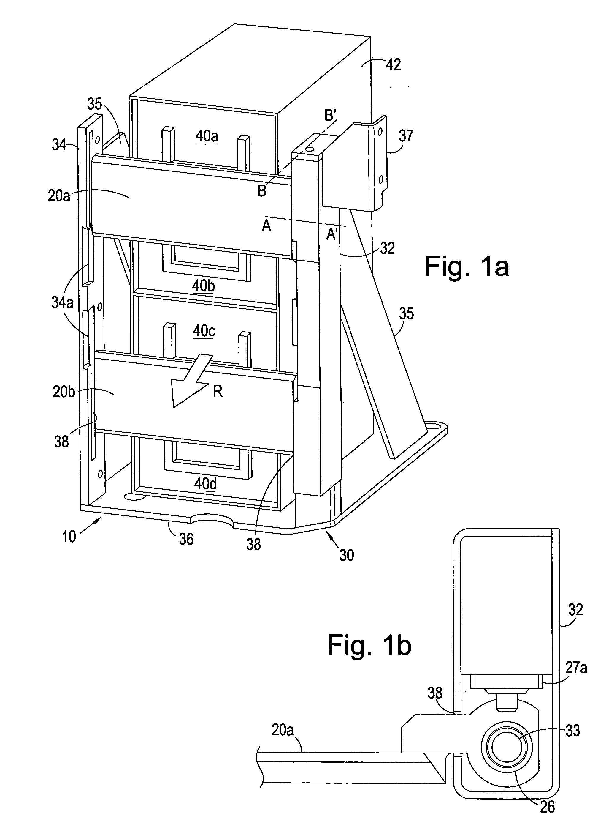
[0028]Referring to FIG. 1a, an apparatus 10 for securing cassettes housed within an automatic teller machine (ATM) is shown. In more detail, the apparatus 10 includes: two barriers 20, an upper barrier 20a and a lower barrier 20b; and a supporting structure 30 for supporting the barriers 20. The apparatus 10 is installed inside the ATM. Each barrier 20 of the apparatus 10 is arranged to extend across the front of a pair of adjacent cassettes 40 stacked within the ATM. The cassettes 40 (a, b, c and d) are slotted into a cassette housing 42, the cassette housing 42 being installed inside the ATM.

[0029]In order for a cassette 40 to be removed, it must be pulled out along a removal path in a direction indicated by arrow R.

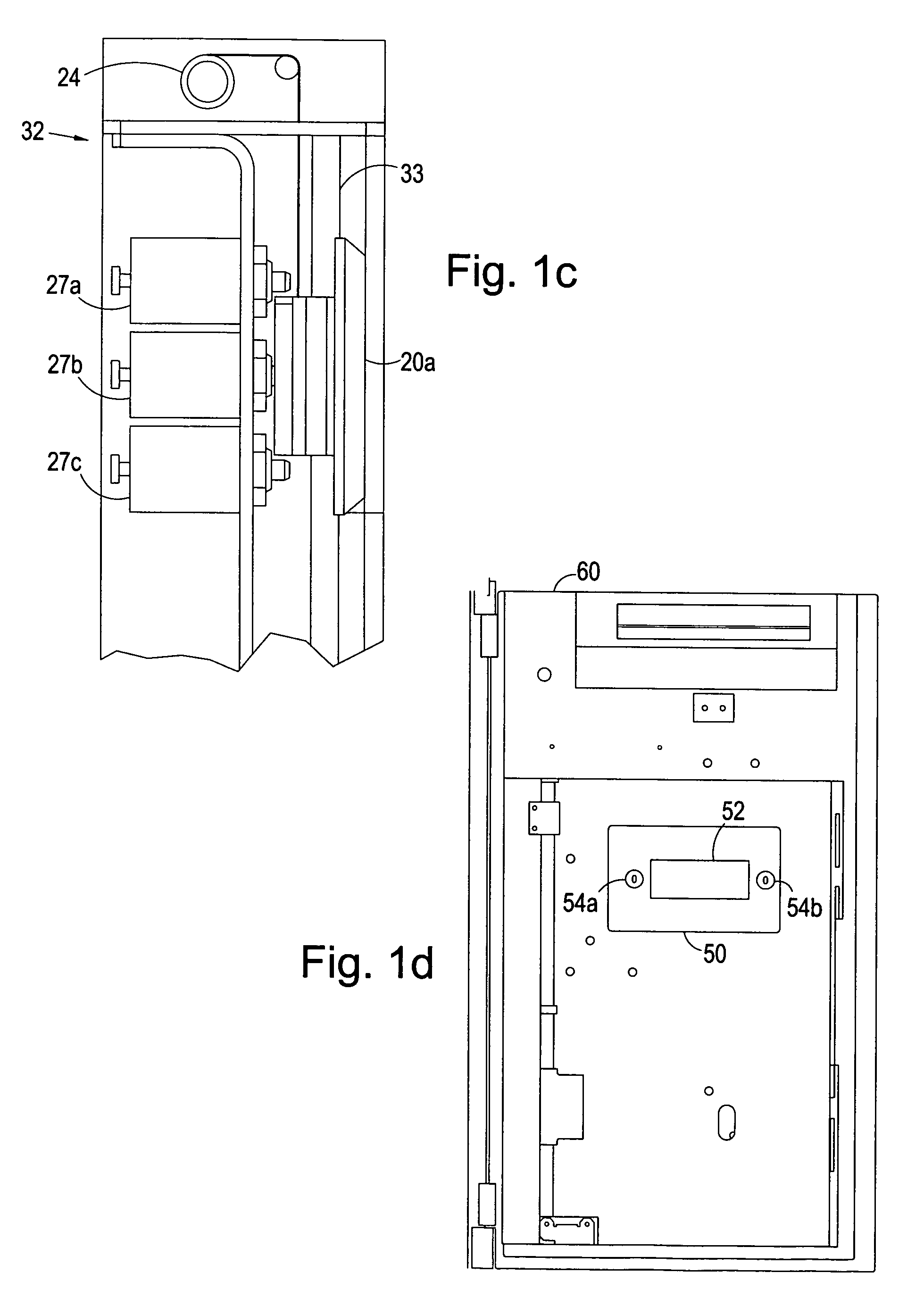
[0030]The supporting structure 30 comprises a vertical beam 32 spaced apart from a keeper plate 34, both mounted on a base mounting plate 36. The vertical beam 32 has two channels 38 formed vertically along inner sides thereof and the keeper plate 34 has two channels 3...


PUM


Abstract

The present invention, relates to an apparatus for securing cassettes housed within an automatic teller machine (ATM). The apparatus comprises at least one barrier and a supporting structure for supporting at least one barrier. Each barrier is formed and arranged to be associated with a pair of adjacent cassettes and to be movable between a first position in which the barrier prevents removal of a pair of adjacent cassettes in use of the apparatus along their respective removal paths. The barrier is moveable to a second position in which the barrier prevents removal of one cassette of the pair of adjacent cassettes along its removal path and to a third position in which the barrier prevents removal of the other cassette of the pair of adjacent cassettes along its removal path. In use, only one cassette of a pair of adjacent cassettes is removable along its removal path when the barrier is in the second or third position. The apparatus is further formed and arranged so that the barrier (or barriers) can be moved to a ‘service’ position so that both cassettes can be accessed and removed along their removal paths and for servicing of the ATM.

Description

CROSS-REFERENCE TO RELATED APPLICATIONS[0001]This application is a U.S. national phase filing under 35 U.S.C. §371 of PCT / GB2009 / 000275 filed Feb. 2, 2009, both of which claim priority from United Kingdom Application No. GB 0801848.3 which was filed on Feb. 1, 2008, both of which are incorporated herein by reference.FIELD OF THE INVENTION[0002]The present invention relates to a security system and apparatus for use with an automatic teller machine (ATM).BACKGROUND OF THE INVENTION[0003]ATMs are well known devices that allow a user to withdraw cash from a bank account without the need for a teller. ATMs are designed to be highly secure as large amounts of cash are stored therein. A standard ATM includes currency cassettes, in which banknotes are loaded. These currency cassettes are slotted into a housing to form a stack, and each currency cassette can only be removed from the housing by sliding it out in a removal path in a similar fashion to sliding open a drawer. This stack is hous...

Claims


Application Information

Patent Timeline
IPC IPC(8): E05B65/44E05G1/00E05B65/467
CPCE05B47/0603E05B65/467E05B47/0002E05B2047/0007E05B2047/0068G07F19/20Y10T70/5009Y10T70/5097Y10T70/5128
Inventor CALDER, PAUL ROBERT
Owner SCOTIA SAFES
Why Eureka
Try Eureka