
Exhaust muffler for internal combustion engines

a technology for exhaust mufflers and internal combustion engines, which is applied in the direction of machines/engines, instruments, heat measurement, etc., can solve the problems of low noise reduction, low efficiency in reducing noise, and increased back pressure of exhaust, so as to achieve economic construction and reliable operation

Active Publication Date: 2013-05-14
BORLA DAVID
View PDF10 Cites 30 Cited by
  • Summary
  • Abstract
  • Description
  • Claims
  • Application Information

AI Technical Summary

Benefits of technology

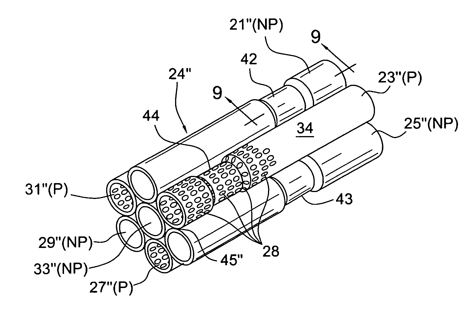
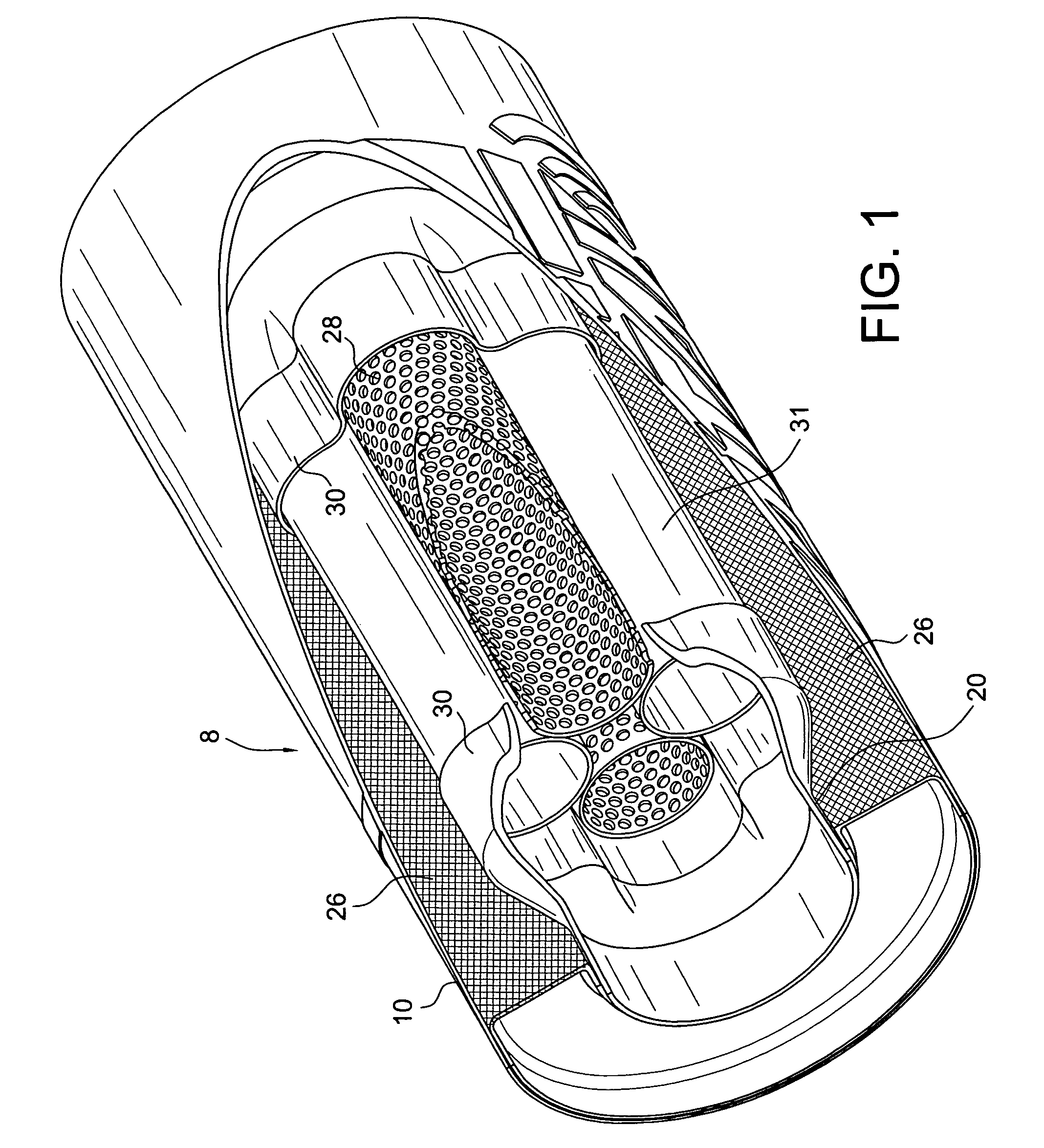
The present invention is a small muffler for reducing noise in exhaust gas from engines. It uses a structure similar to resonators and throttling mufflers while creating only low back pressure. The muffler allows for tuning to create a unique sound for each car. The muffler has a unique design with nested tubes that helps achieve unrestricted flow and minimal back pressure. The tubes are arranged in a helical bundle, which allows for longer tubes without increasing the overall length of the muffler. Overall, the invention allows for a compact muffler that reduces noise while still allowing for unrestricted flow.

Problems solved by technology

The problem of muffling the noise generated or emitted in the exhaust gases from the internal combustion engine is well known.
These mufflers are advantageous in that they provide lower back pressure, but are not very effective in reducing the level of noise.
This type of muffler does reduce noise to some extent, however, the back pressure of the exhaust tends to increase due to the blocked exhaust flow.

Method used


Image

  • Exhaust muffler for internal combustion engines
  • Exhaust muffler for internal combustion engines
  • Exhaust muffler for internal combustion engines

Examples


Embodiment Construction

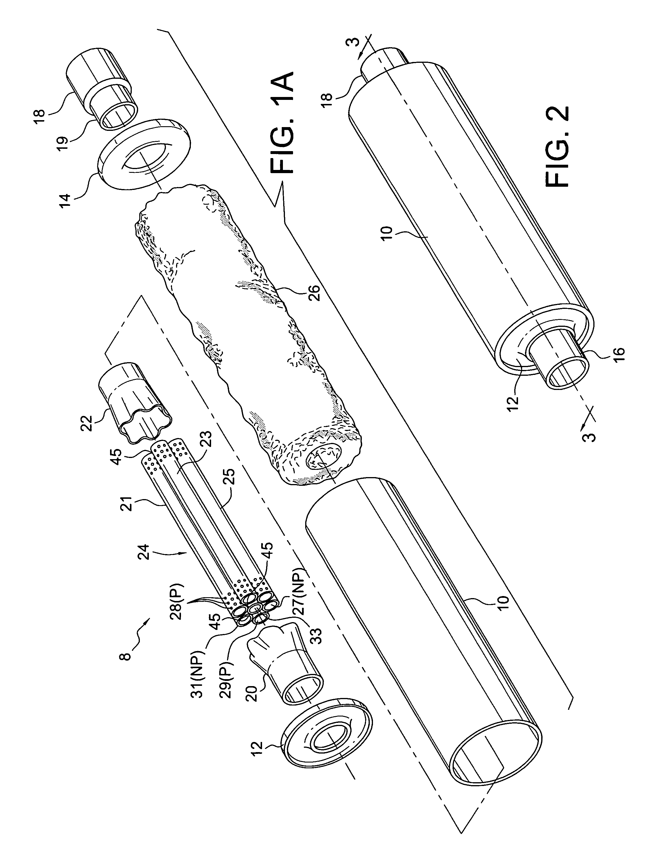
[0032]FIGS. 1 and 2 illustrate a muffler 8 of any configuration which includes a generally cylindrical shell (casing, can or housing) 10 with open ends. Secured to and telescoped within each end of shell 10 are dual, flanged end caps 12 and 14 each having a center flanged opening therein for connection with respectively associated inlet and outlet ducts 16 and 18. Inlet and outlet ducts 16 and 18 have reduced diameter portions 17 and 19, respectively, adapted to be telescopically received within cylindrical portions 37 and 39 of entrance and exit collars 20 and 22, respectively. It is also contemplated to make the entrance duct 16 and entrance collar 20 as one piece, as well as the exit duct 18 and exit collar 22. In this instance, the inlet and outlet ducts 16 and 18 would have a constant diameter equal to portions 37 and 39 of the entrance and exit collars. Of course, the openings in end caps 12 and 14 would be sized to accommodate the dimensions of the entrance and exit duct / coll...


PUM


Abstract

A new and improved muffler for use particularly with internal combustion engines which utilizes a tube assembly composed of a plurality of laterally nested perforated and non-perforated tubes in direct supporting lateral engagement with each other wherein the perforations provide direct communication of exhaust gases therebetween and wherein the tube assembly is supported at opposite ends by frustoconical entrance and exit collars, the larger ends of the collars being crimped or otherwise secured thereto providing a sealed connection.

Description

[0001]This application claims priority under 35 U.S.C. 119(e)(1) based on Applicants Provisional U.S. Patent Application Ser. No. 61 / 402,458 filed 8-30-10 and titled “AUTO MUFFLER CONSTRUCTION”.BACKGROUND OF THE INVENTION[0002]This invention relates in general to silencing high velocity air or gas exhaust flow to atmosphere or the like, and is particularly directed to mufflers for use with internal combustion engines and the like.[0003]The problem of muffling the noise generated or emitted in the exhaust gases from the internal combustion engine is well known. Many types of mufflers and noise reducing devices have been developed to address this problem. One type of muffler generally referred to an absorption muffler directs exhaust gas straight through a perforated tube with a uniform configuration from end to end with sound deadening material such as glass fibers between the tube and an outer housing. These mufflers are advantageous in that they provide lower back pressure, but are...

Claims


Application Information

Patent Timeline
Patent Type & Authority Patents(United States)
IPC IPC(8): F01N1/24
CPCF01N1/083F01N2330/36F01N2470/10F01N2470/24
Inventor BORLA, ALEXANDER
Owner BORLA DAVID
Learn More