User operable pointing device such as mouse

a user-operated, mouse-like technology, applied in the direction of instruments, computing, electric digital data processing, etc., can solve the problems of more expensive devices using new technology solutions, no remarkable advantages, and inability to realise a computer mouse using accelerometers for motion detection, etc., to achieve the effect of cheaper manufacturing and lower manufacturing costs

Active Publication Date: 2013-05-14
UNIRAJA OU
View PDF31 Cites 11 Cited by
  • Summary
  • Abstract
  • Description
  • Claims
  • Application Information

AI Technical Summary

Benefits of technology

[0012]The device of the invention is very cheap to manufacture, The mechanics of the device is very simple and durable. The ball shape is ideal in rigidity versus weight. There are only a few components which will all be basic standard components in the electronics industry. When high-volume mass production starts, it will become economically possible to integrate the most of the needed components in a special Bluetooth unit, and the manufacturing costs may be even lower.

Problems solved by technology

There have been problems to realise a computer mouse utilising accelerometers for motion detection.
Another problem is that the solutions still include a lot of separate parts assembled mechanically together to form the device.
The devices using new technical solutions are more expensive than the conventional ones but, in fact, give no remarkable advantages.
In our opinion, the most serious problem is the lack of such a novel concept of a user operable device, e.g. mouse, which would make possible to utilise the above considered new technologies for realising a simple and low cost device which could be a new basic solution displacing the conventional mechanical and optical mice.

Method used


Image

  • User operable pointing device such as mouse
  • User operable pointing device such as mouse
  • User operable pointing device such as mouse

Examples


example 1

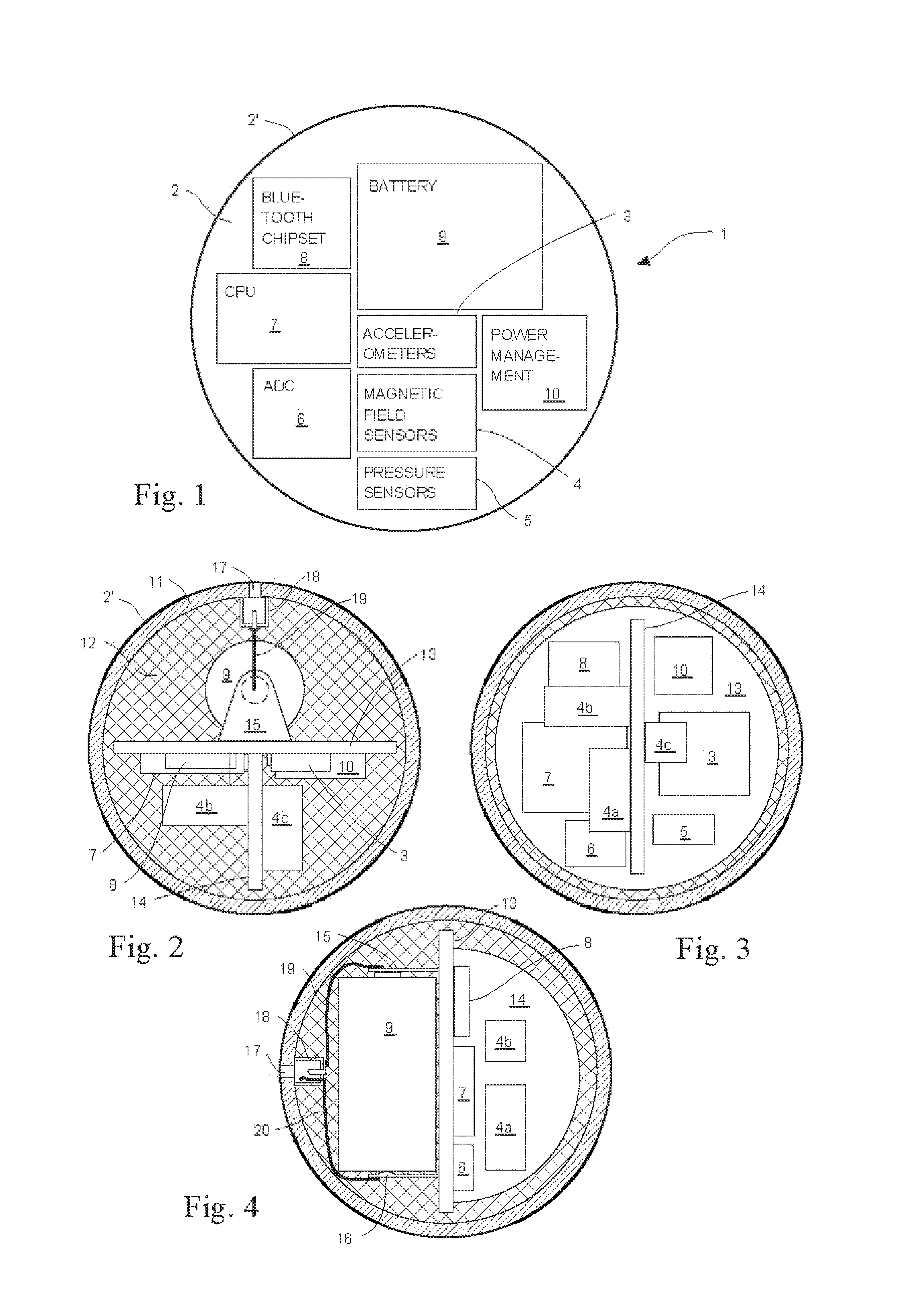
[0035]Step 1: The CPU 7 opens or otherwise establishes a communication channel to the electric appliance to be controlled. The appliance may be a computer, mobile phone, PDA, data projector, toy, TV set, car, for example. Step 1 may be skipped if the appliance or the used communication method does not require initialisation.

[0036]Step 2: The CPU 7 establishes reference direction of the movement of the ball device. It can be done via a user input by shortly rotating the apparatus to a pre-determined direction or by placing the apparatus on a certain “start orientation” where some visible clues of the orientation of the ball are viewed by the user, for example.

[0037]Step 3: The CPU 7 reads sensor data obtained from the sensors 3, 4 and 5,

[0038]Step 4: The CPU 7 performs the necessary filtering functions to process the sensor data for separating the essential data from noise.

[0039]Step 5: The CPU 7 calculates the movement values of the ball device from the essential sensor data, This i...

example 2

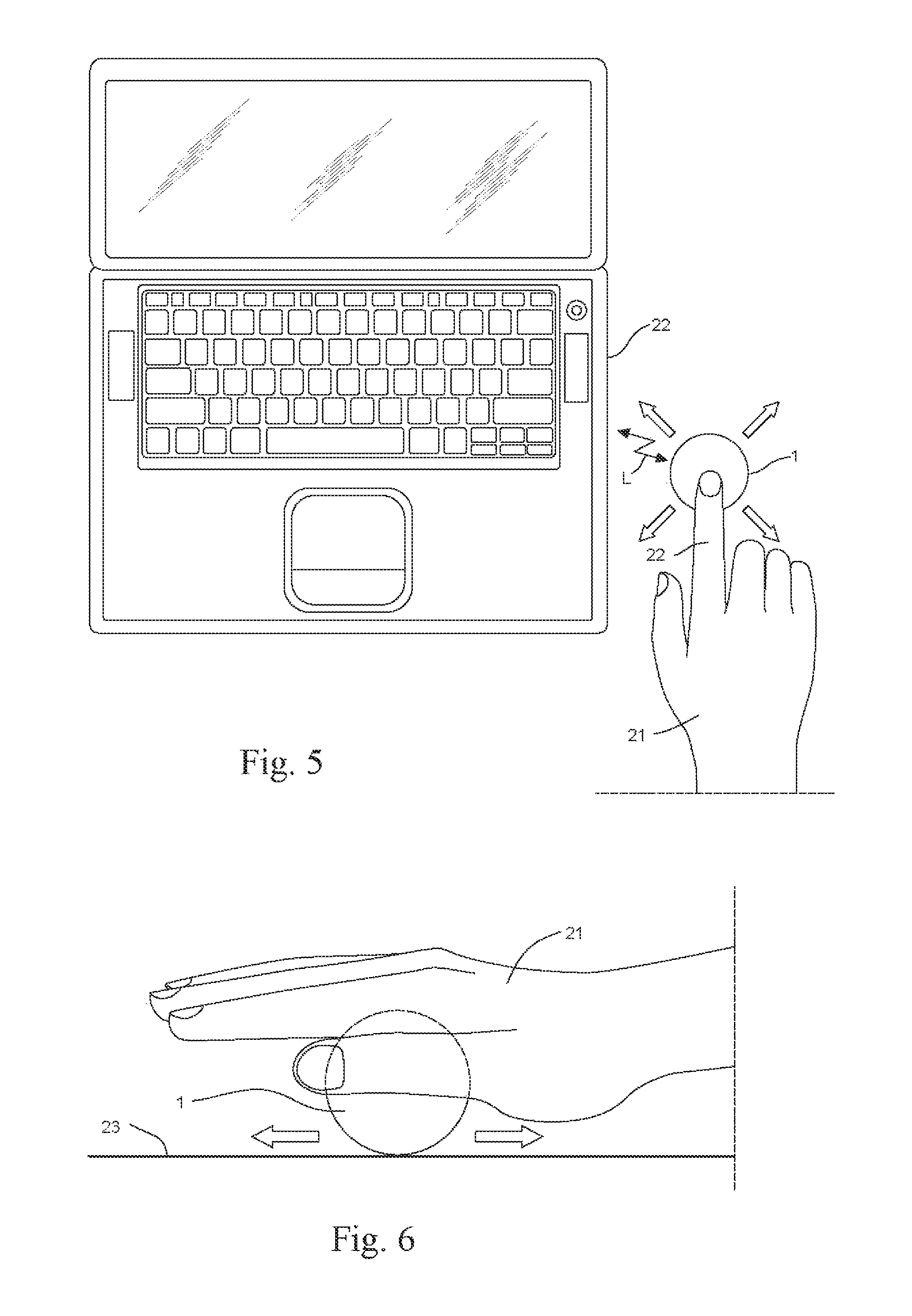
[0045]This example describes the operation of the ball device as a user operable device for measuring a distance and sending the measurement results to a suitable electric appliance.

[0046]Step 1: The CPU 7 opens or otherwise establishes a communication channel to a receiving electric appliance. Step 1 may be skipped if the receiving device or the used communication method does not require initialisation.

[0047]Step 2: The CPU 7 reads sensor data obtained from the sensors 3, 4 and 5.

[0048]Step 3: The CPU 7 performs the necessary filtering functions to process the sensor data for separating the essential data from noise.

[0049]Step 4: The CPU 7 calculates the movement values of the ball device from the essential sensor data. This is done by converting accelerometer or magnetic field orientation values into motion and rotational co-ordinates of the device.

[0050]Step 5: The CPU sends the calculated ball device movement values via the communication channel to the receiving electric applian...


PUM


Abstract

A user operable device for control of or communication with an electric appliance, in particular a user operable pointing device such as a mouse, including electrical components and circuits including sensor elements, processing elements and wireless communication elements for detecting movements including at least rotational movements of the device, producing data related to the movements and transmitting the data to the electric appliance, is characterized in that the device (1) is essentially a ball (2) including outer surface (2′) for free rolling and for receiving influences of physical effects on the surface and the device, and that the electrical components and circuits (3, 4, 5, 6, 7, 8, 9, 10) are inside the ball (2) in integrated relationship with the ball. The invention concerns also a user interface including the user operable device of the invention.

Description

FIELD OF THE INVENTION[0001]The present invention relates to a user operable device for control of or communication with an electric appliance, in particular to a user operable pointing device such as a mouse. The electric appliance may be a computer, PDA, mobile phone, GPS device, game device, television set, car entertainment system or personal exercise monitoring device, for example.BACKGROUND OF THE INVENTION[0002]One of the most common interfaces between a user and a computer or a computer controlled device is a conventional mouse detecting 2D movements of the mouse on a suitable flat surface and providing corresponding signals to a computer for moving a pointer on a display. Despite of that, a conventional mouse includes buttons for positioning a pointer, selecting data, opening and closing windows or menus for further selections, stating and closing programs or applications and entering commands in various situations. Furthermore, a computer mouse may include other functions,...

Claims


Application Information

Patent Timeline
Patent Type & Authority Patents(United States)
IPC IPC(8): G09G5/00G06F3/033G06F3/0354G06F3/048G06F3/0485G06F3/0486
CPCG06F3/0354G06F3/03543G06F3/03549G06F3/0485G06F3/0486
Inventor VAANANEN, JOHANNESRYTKY, JUHA
Owner UNIRAJA OU
Why Eureka
Try Eureka