
Data center module

a data center module and data center technology, applied in the field of data center modules, can solve the problems of 5 times the power of the cooling system, the heat sinking method using an air conditioning system consumes too much energy, and the power consumption of the cooling system is maintained high

Active Publication Date: 2013-05-14
IND TECH RES INST
View PDF35 Cites 34 Cited by
  • Summary
  • Abstract
  • Description
  • Claims
  • Application Information

AI Technical Summary

Benefits of technology

The data center module described in this patent is designed to cool down multiple servers in a rack. It consists of two chambers and a heat pipe. The rack is placed in the first chamber, and the second chamber is located next to the first. The heat pipe picks up the heat from the servers in the first chamber, carries it to the second chamber, and then releases it there. This heat sink effect is achieved without direct contact between the external air and the servers, reducing the risk of pollution.

Problems solved by technology

That is, several or tens of high heat-generation racks is filled in the whole data center, such that the air conditioning power consumption required by a data center is maintained high.
As a result, the heat sinking manner using an air conditioning system consumes too much energy.
That is, the data center generally needs to cost additionally 1 to 1.5 times of the power for the cooling system, and this is undoubtedly a waste of cost.
However, impurities such as sulfide or nitride exist in the external air, so that the simple introduction of the external air causes pollution to the electronic elements in the data center by the external air.
As a result, this cooling manner easily causes the failure of the electronic elements in the data center due to pollution.

Method used


Image

  • Data center module
  • Data center module
  • Data center module

Examples


Embodiment Construction

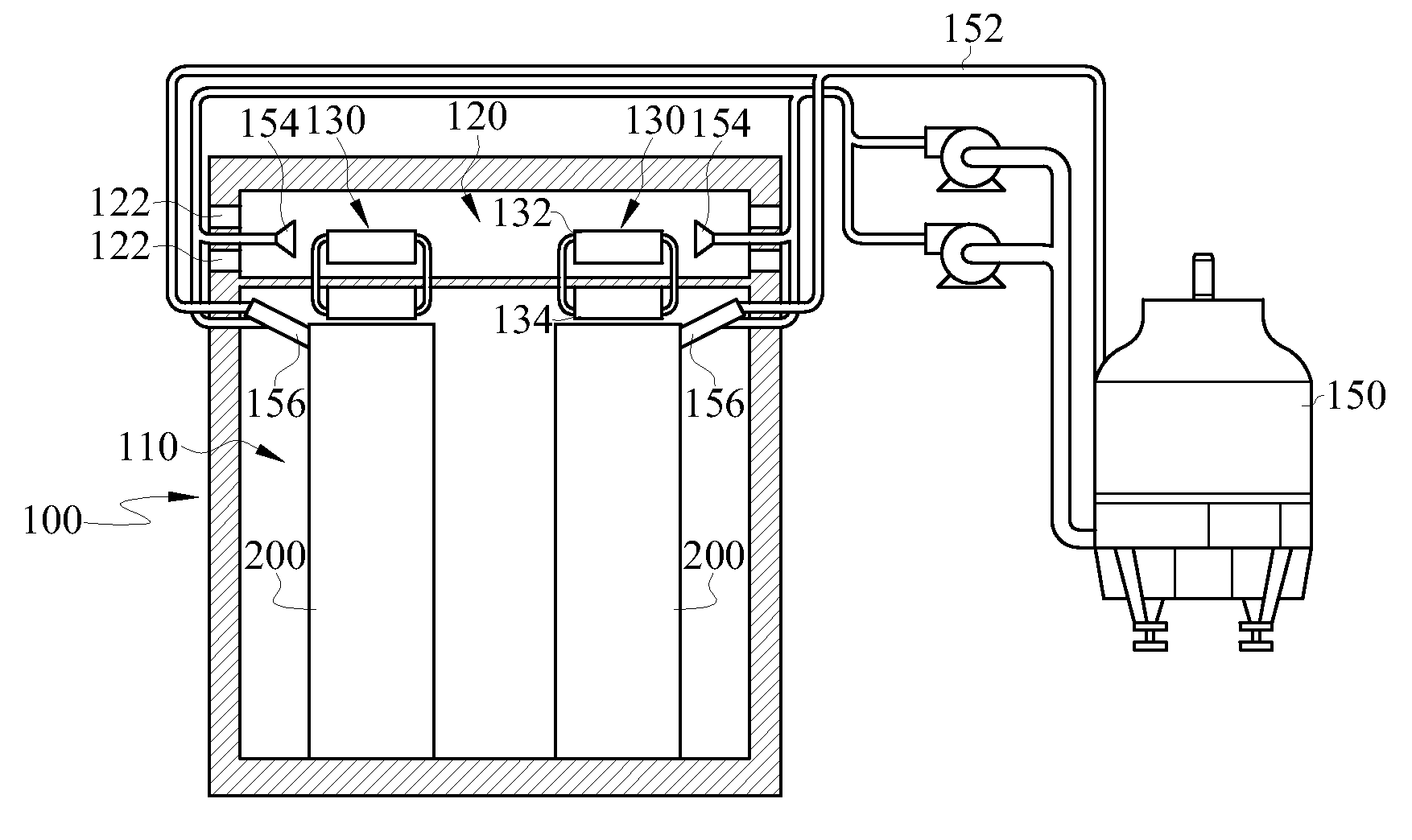
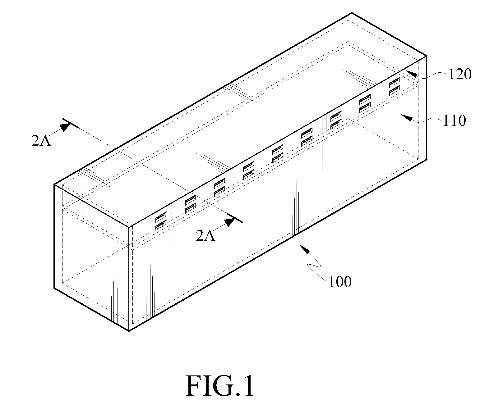
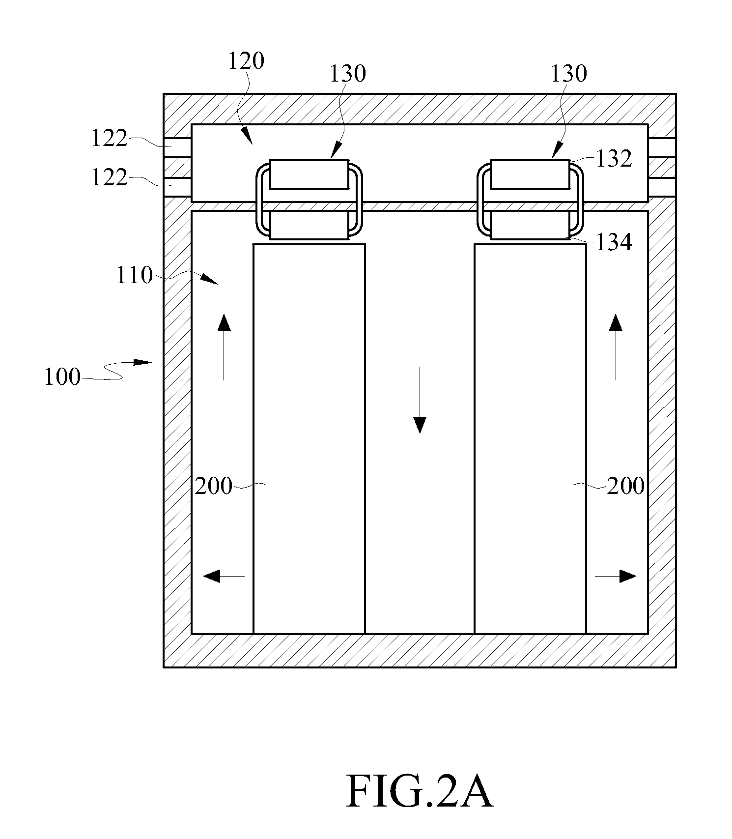
[0028]FIG. 1 is a schematic view of a data center module according to an embodiment of the present disclosure, and FIG. 2A is a flat side view of a data center module according to an embodiment of the present disclosure along a section line 2A as shown in FIG. 1.

[0029]A data center module 100 according to the embodiment of the present disclosure is used for heat sinking of sever in a rack of sever 200.

[0030]The data center module 100 is generally in the configuration of a cabinet, so as to be conveniently delivered to all places. The data center module 100 can be divided into a first chamber 110 and at least one second chamber 120. The first chamber 110 is adjacent to the second chamber 120. In this embodiment, one second chamber 120 exists, and is positioned above the first chamber 110; however, the number of the second chambers 120 and the positions of the first chamber 110 and second chambers 120 are not intended to limit the present disclosure. For example, in other embodiments ...


PUM


Abstract

A module for data center is presented, which is used for heat sinking of a heat source. The module for data center includes a first chamber, a second chamber, and a heat pipe. The heat source is positioned in the first chamber. The second chamber is adjacent to the first chamber. In addition, the heat pipe has an evaporation end positioned inside the first chamber and a condensation end positioned inside the second chamber. The heat pipe absorbs the heat energy in the first chamber with the evaporation end, transfers the heat energy to the condensation end, and eliminates the heat energy with the condensation end.

Description

CROSS-REFERENCE TO RELATED APPLICATIONS[0001]This non-provisional application claims priority under 35 U.S.C. §119(a) on Patent Application No(s). 099137335 filed in Taiwan, R.O.C. on Oct. 29, 2010, the entire contents of which are hereby incorporated by reference.BACKGROUND[0002]1. Field[0003]The present disclosure relates to a data center module, and more particularly to a data center module capable of preventing an electronic device from pollution by air.[0004]2. Related Art[0005]In a conventional cooling method for a data center, an air conditioning system of a common house or an office building is generally used, or a design of cold and heat channels is introduced. For example, in the air conditioning system, a coolant is compressed by a compressor into a high-temperature and high-pressure coolant gas, which is fed into a condenser. Then, a cooling fluid is fed into the condenser by a cooling water tower in combination with a pump for heat exchange, such that the high-temperatu...

Claims


Application Information

Patent Timeline
Patent Type & Authority Patents(United States)
IPC IPC(8): H05K7/20
CPCH05K7/20827H05K7/208H05K7/20754
Inventor WU, HSI SHENGCHIANG, HSU CHENGHUNG, KUO SHUSUN, KUEL KER
Owner IND TECH RES INST
Learn More