Method for manufacturing grinding wheel having depressions on grinding surface thereof

a manufacturing method and technology of grinding wheels, applied in the direction of manufacturing tools, grinding devices, other chemical processes, etc., can solve the problems of easy dropout of superabrasive grains, difficulty in processing inclined grooves or hole-shaped depressions, etc., and achieves high durability, easy manufacturing, and reduced retentivity

Inactive Publication Date: 2013-05-21
JTEKT CORP +1
View PDF14 Cites 1 Cited by
  • Summary
  • Abstract
  • Description
  • Claims
  • Application Information

AI Technical Summary

Benefits of technology

[0014]According to the invention described in claim 1, the plurality of depressions are formed on the non-baked grinding chip, and then the grinding chip is baked. The machining process performed on the baked chip reduces the retentivity of the superabrasive grains exposed on the grinding surface at the inside wall portions of the depressions. However, in the present invention, as it is not necessary to perform the machining process on the baked chip to form the depressions, the retentivity of the superabrasive grains exposed on the grinding surface at the inside wall portions of the depressions is not reduced. Thus, the highly durable grinding wheel having superabrasive grains strongly combined with the bond can be easily manufactured at a low cost.
[0015]According to the invention described in claim 2, the non-baked grinding chip is formed by overlaying the substrate layer on the inner surface of the abrasive grain layer, and then by integrally press-molding the abrasive grain layer and the substrate layer in an arcuate shape. Subsequently, the grooves inclined relative to the circumferential direction of the grinding wheel are formed on the abrasive grain layer of the non-baked grinding chip. In the baked grinding chip, the superabrasive grains are strongly bound by the bond through a baking process. However, as the superabrasive grains are weekly bonded by the bond in the non-baked chip that is not yet baked, wear of a tool for forming the grooves is reduced, and the inclined grooves are easily formed at a low coat. Furthermore, as the grinding chip is baked after the inclined grooves are formed thereon, the superabrasive grains exposed from the bond due to the machining process are coated and bonded with the bond which is molten while baking, and thereby the retentivity of the superabrasive grains is not reduced by the machining process. Plural grinding chips are adhered to the core. Therefore, the grinding wheel having the inclined grooves, which has strong resistance to wear, can be easily manufactured at a low cost.
[0016]According to the invention described in claim 3, because the inclined grooves are formed in the abrasive grain layer such that the inclined grooves reach to the substrate layer from the grinding surface, the entire thickness of the abrasive grain layer can be effectively used for grinding. Consequently, the grinding wheel life can be elongated.
[0017]According to the invention described in claim 4, because the inclined grooves are formed in such a manner that a tool for forming the inclined groove is linearly moved relative to the non-baked grinding chip in a direction of the inclination angle of the inclined groove, processing time can be shortened and thus the inclined grooves can be easily formed compared with a method where the inclined grooves are formed in a spiral shape.
[0018]According to the invention described in claim 5, the non-baked grinding chip is formed in such a manner that a plurality of inclined groove forming plates made of carbon or resin for forming the inclined grooves are disposed at a grinding surface forming surface of a press-mold die, the particles for the abrasive grain layer are put into the press-mold die, and the particles for the substrate layer are put onto the particles for the abrasive grain layer in the press-mold die. The particles for the abrasive grain layer and the particles for the substrate layer are integrally press-molded in such a manner that the substrate layer to be formed is not divided by the inclined groove forming plate, and the inclined grooves are formed through the abrasive grain layer. Therefore, the process in which the inclined grooves are formed can be eliminated. The machining process performed on the baked chip reduces the retentivity of the superabrasive grains exposed on the grinding surface at the inside wall portions of the inclined grooves. However, as it is not necessary to perform the machining process on the baked chip to form the inclined grooves, the retentivity of the superabrasive grains exposed on the grinding surface at the inside wall portions of the inclined grooves is not reduced by the machining process. Thus, the highly durable grinding wheel having superabrasive grains combined with the bond can be easily manufactured at a low cost. In addition, because the inclined groove forming plates made of carbon or resin can be burned away at the high temperature when the grinding chip is baked, the process in which inclined groove forming plates are removed from the non-baked grinding wheel can be eliminated, thereby improving the manufacturing efficiency. When the inclined groove forming plates are burned away, the edge of the inclined grooves of the grinding chip is not damaged or deformed, thereby improving the quality of the grinding chip.
[0019]According to the invention described in claim 6, the non-baked grinding chip is formed in such a manner that a plurality of inclined groove forming plates made of metal for forming the inclined grooves are disposed at a grinding surface forming surface of a press-mold die, the particles for the abrasive grain layer are put into the press-mold die, and the particles for the substrate layer are put onto the particles for the abrasive grain layer in the press-mold die. The particles for the abrasive grain layer and the particles for the substrate layer are integrally press-molded in such a manner that the substrate layer is not divided by the inclined groove forming plate. Then, the integrally formed abrasive grain layer and substrate layer are removed from the press-mold die. The plurality of inclined groove forming plates are removed from the abrasive grain layer, so that the grooves inclined relative to the circumferential direction of the grinding wheel are formed on the abrasive grain layer. Therefore, the process in which the inclined grooves are formed can be eliminated. The machining process performed on the baked chip reduces the retentivity of the superabrasive grains exposed on the grinding surface at the inside wall portions of the inclined grooves. However, as it is not necessary to perform the machining process on the baked chip to form the inclined grooves, the retentivity of the superabrasive grains exposed on the grinding surface at the inside wall portions of the inclined grooves is not reduced. Thus, the highly durable grinding wheel having superabrasive grains combined with the bond can be easily manufactured at a low cost.

Problems solved by technology

In order to form the grooves on the grinding surface of the grinding wheel, if the inclined grooves are formed by machining process on the grinding surface of a baked grinding chip adhered to the core of the grinding wheel, it is difficult to process the inclined grooves or the hole-shaped depressions by reason of, for example, remarkable wearing of the grinding wheel for forming the grooves or depressions because the inclined grooves or hole-shaped depressions are formed by the machining process at the abrasive grain layer in which the superabrasive grains are maintained by strong bond.
In addition, if the inclined grooves or the hole-shaped depressions are formed through the machining process on the baked abrasive grain layer of the grinding wheel, a retentivity of the superabrasive grains exposed on the grinding surface at a side wall portion of the inclined groove or at an inner wall portion of the hole-shaped depression is reduced by the machining process, and thus it makes the superabrasive grains easily dropout.

Method used


Image

  • Method for manufacturing grinding wheel having depressions on grinding surface thereof
  • Method for manufacturing grinding wheel having depressions on grinding surface thereof
  • Method for manufacturing grinding wheel having depressions on grinding surface thereof

Examples


first embodiment

[0053]Described hereinafter is a method (the first embodiment) for manufacturing the grinding chip 11 with reference to FIG. 10A. An outer die 41 has a rectangular through cavity. A lower die 42 is fitted in the bottom portion of the through cavity of the outer die 41. A concavity 42a is formed on an upper surface of the lower die 42. The concavity 42a has an arcuate shape corresponding to an arcuate surface of the grinding chip 11 forming an outer periphery of the grinding wheel 10. The outer die 41 and the lower die 42 constitute a press-mold die for molding the grinding chip, and the surface of the concavity 42a constitutes a grinding surface forming surface of the press-mold die for molding the grinding chip. Particles 44 for the abrasive grain layer are put onto the lower die 42 in the outer die 41, and the particles 44 are leveled into uniform thickness (process 51 in FIG. 11). Then, as illustrated in FIG. 10B, a first upper die 45 as a press die is moved downward along the in...

second embodiment

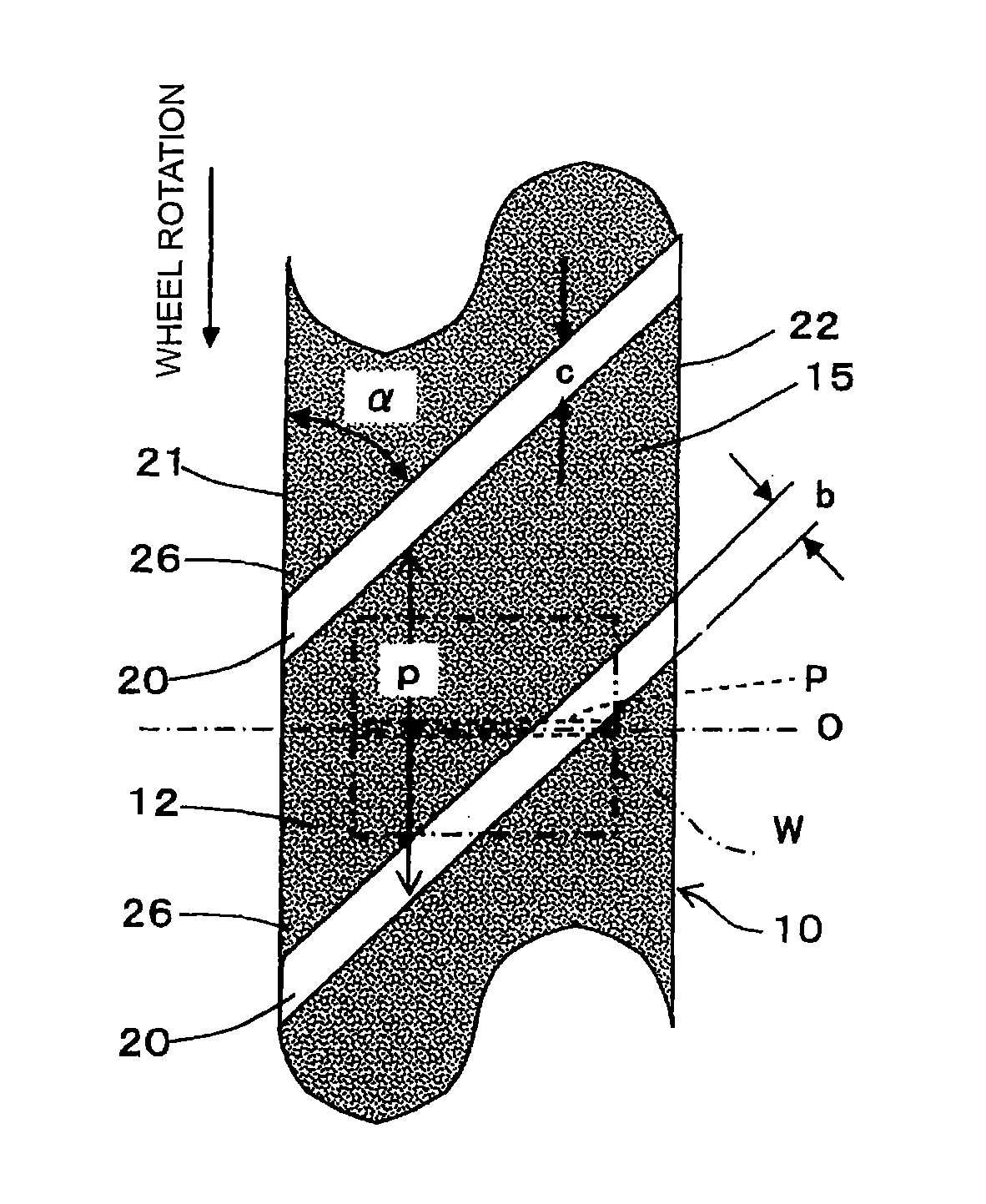
[0066]In the method the inclined grooves 20 are formed on the grinding surface of the grinding chip 11 by press-molding. As illustrated in FIG. 14 and FIG. 15, a lower die 82 is inserted into a bottom portion of a rectangular through cavity that is formed through an outer die 81. An arcuate concavity 82a for press-molding an arcuate surface of a grinding chip 11 is formed on an upper surface of the lower die 82. The arcuate surfaces of grinding chips 11 compose an outer periphery of the grinding wheel 10. A plurality of mounting grooves corresponding to the inclined grooves 20 are formed on the lower die 82. And a plurality of inclined groove forming plates 83 for forming the plurality of inclined grooves are detachably fitted into the mounting grooves, so that the inclined groove forming plates 83 protrude upwardly from the bottom surface of the concavity 82a. The inclined groove forming plates 83 are made of materials such as carbon and are fitted into the mounting grooves to sta...

third embodiment

[0079]According to the method for manufacturing the grinding chip 11 in accordance with the third embodiment, the plurality of hole-shaped depressions 90 are formed on the grinding chip 11 by press-molding. As illustrated in FIG. 19, a lower die 92 is fitted in a bottom portion of a rectangular through cavity formed through an outer die 91. An arcuate concavity 92a for press-molding an arcuate surface of a grinding chip 11 is formed on an upper surface of the lower die 92. The arcuate surfaces of grinding chips 11 compose an outer periphery of the grinding wheel 10. A plurality of mounting holes corresponding to the hole-shaped depressions 90 are formed on the lower die 92. And a plurality of pin members 93 for forming the plurality of hole-shaped depressions are detachably mounted to the mounting holes respectively, so as to protrudes upwardly from the bottom surface of the concavity 92a. The pin members 93 are made of materials such as carbon.

[0080]First, as illustrated in FIG. 19...


PUM

PropertyMeasurementUnit
thicknessaaaaaaaaaa
thicknessaaaaaaaaaa
thicknessaaaaaaaaaa

Abstract

A grinding wheel is manufactured such that (a) any one of particles for an abrasive grain layer and particles for a substrate layer are put into the press-mold die, and other particles are put onto the particles in the press-mold die, and then the substrate layer and the abrasive grain layer are integrally press-molded to form a non-baked grinding chip with an arcuate shape; (b) depressions are formed on the abrasive grain layer of the non-baked grinding chip; (c) the grinding chip on which the depressions are formed is baked; and (d) the plurality of baked-grinding chips are adhered to a core of the grinding wheel.

Description

TECHNOLOGICAL FIELD[0001]The present invention relates to a method for manufacturing a grinding wheel having depressions on a grinding surface thereof, wherein depressions with a shape of inclined groove or a hole are formed on segment type grinding chips which are adhered to a core of the grinding wheel.BACKGROUND ART[0002]A grinding wheel disclosed in Japanese Patent Laid-open Publication No. 2000-354969 ([0007], [0026], FIG. 1), includes an abrasive grain layer in which inclined grooves are formed on a grinding surface formed on a periphery of the abrasive grain layer. More specifically, the abrasive grain layer contains superabrasive grains such as diamond or cubic boron nitride, and is adhered to a periphery surface of a disc-type core that is rotated about its axis. The inclined grooves have a predetermined width and depth, and are inclined at an angle of approximately 25 to 45 degrees to the axis of the core. Compared with the conventional grinding wheel having no grooves, th...

Claims


Application Information

Patent Timeline
Patent Type & Authority Patents(United States)
IPC IPC(8): B24D11/00B24D99/00
CPCB24D3/14B24D5/06B24D5/10B24D18/0009B24D99/005
Inventor SOMA, SHINJIMORITA, KOJIINAGAKI, TOMOHIROMOROTO, TAKAYUKISUGITA, KAZUHIKOIMAI, TOMOYASUKUNIHIRO, YASUJI
Owner JTEKT CORP
Why Eureka
Try Eureka