Electrode wire for wire electrical discharge machining, method for manufacturing the same, and method for electrical discharge machining using the same

a technology of electrical discharge machining and electrode wire, which is applied in the direction of electrical-based machining electrodes, manufacturing tools, transportation and packaging, etc., can solve the problems of poor surface finish of workpieces, contact area, and inability to manufacture, so as to prevent the degradation of machining accuracy

Inactive Publication Date: 2013-05-21
OKI ELECTRICAL CABLE
View PDF15 Cites 8 Cited by
  • Summary
  • Abstract
  • Description
  • Claims
  • Application Information

AI Technical Summary

Benefits of technology

[0026]The present invention has been made to address these problems and has an object to provide an electrode wire for high-speed electrical discharge machining, the wire being capable of preventing machining accuracy degradation caused by wear of zinc, deceleration of the machining speed caused by shorts, and fine streak formation on the machined surface along the traveling direction of the electrode wire.
[0027]The present invention has another object to provide an electrode wire for electrical discharge machining, the wire producing a lesser amount of metal debris derived from the continuously running electrode wire, providing an excellent positioning capability to measure the relative positions between the electrode wire and workpiece, and being unbreakable during handling or machining.
[0029]An electrode wire for wire electrical discharge machining according to the present invention is made by drawing a base wire including a hot-dip galvanized layer formed on a circumference surface of a core made of copper or copper alloy and a diffusion alloy layer generated by thermal interdiffusion between the hot-dip galvanized layer and the core. The hot-dip galvanized layer is drawn based on the difference in malleability and ductility between the hot-dip galvanized layer and the diffusion alloy layer to become a zinc thin film without cracks, and the diffusion alloy layer is crashed by wire drawing into particles to be embedded in the circumference surface of the core such that the zinc thin film and the diffusion alloy layer are integrated with the core and do not fall from the core.
[0035]A method for manufacturing an electrode wire for wire electrical discharge machining according to the present invention includes: preparing a galvanized base wire to be the electrode wire by passing a core made of copper or copper alloy through a plating bath containing zinc at a predetermined temperature for a dipping time to form a zinc layer having a thickness exceeding a predetermined thickness as an outermost layer of the core and to form a diffusion alloy layer through thermal interdiffusion occurring at an interface where the core and the zinc are in contact, and cooling the core with the zinc layer and diffusion alloy layer; and drawing the galvanized base wire. The diffusion alloy layer is crashed into particles and embedded in the circumference surface of the core to integrate the zinc thin film and diffusion alloy layer with the core and prevent the thin film from separating from the core.

Problems solved by technology

Such a solid brass electrode wire cannot be subjected to cold drawing and therefore is impossible to be manufactured.
a. Since wire electrical discharge machining is to cut a workpiece, like a jig saw, by producing discharges between an electrode wire and workpiece, cracks in the surface layer of the electrode wire destabilize the electrical discharges, resulting in poor surface finish of the workpiece;
b. Wire electrical discharge machining apparatuses recognize the relative position between the workpiece and electrode wire by utilizing the electrical conductivity between the workpiece and electrode wire. The presence of the cracks in the surface layer of the electrode wire reduces the contact area and therefore deteriorates the positioning accuracy;
c. Such a brittle surface as is cracked when cold drawn produces a large amount of metal debris due to friction and chafing between the electrode wire and a guide, pulley and some other parts of a machining apparatus that continuously runs the electrode wire for electric discharge machining; and
The cracks in the surface layer decrease reliability of the electrode wire because the wire is likely to break during handling or machining.
However, such a thick zinc layer wears out due to evaporation of zinc and becomes small in diameter during electric discharge machining as shown in FIG. 4, thereby making a difference in width of a machined groove between an inlet side and outlet side and consequently tapering the surface being machined, which is a problem in machining accuracy.

Method used


Image

  • Electrode wire for wire electrical discharge machining, method for manufacturing the same, and method for electrical discharge machining using the same
  • Electrode wire for wire electrical discharge machining, method for manufacturing the same, and method for electrical discharge machining using the same
  • Electrode wire for wire electrical discharge machining, method for manufacturing the same, and method for electrical discharge machining using the same

Examples


embodiment

[0083]Embodiment of the present invention will be described below.

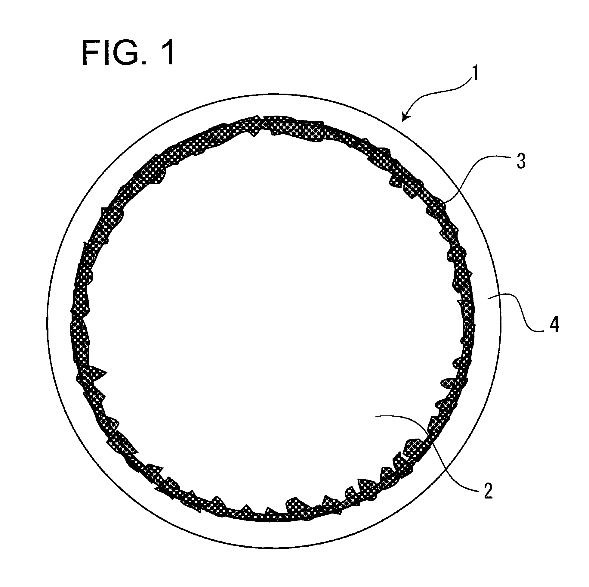
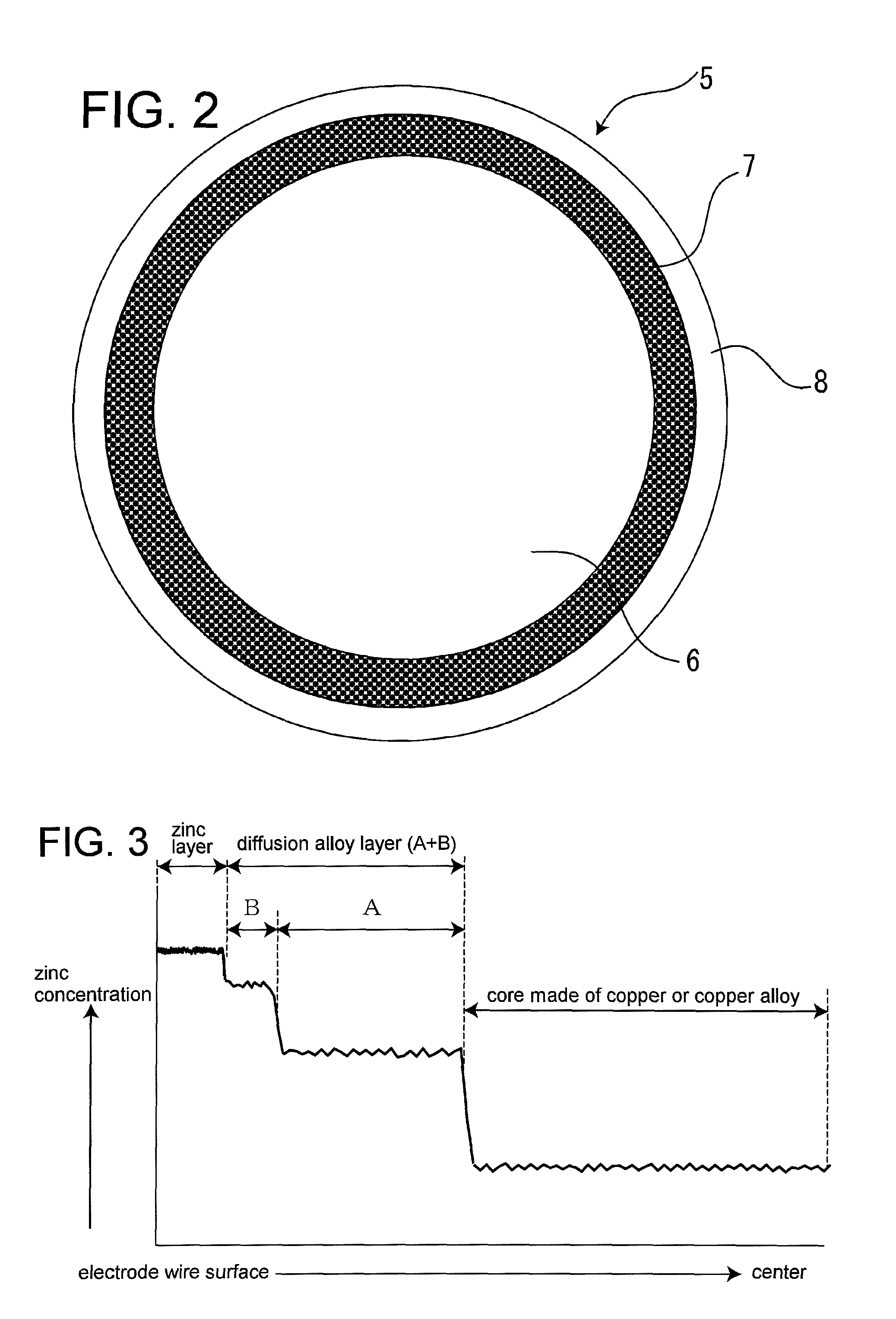
[0084]FIG. 7 schematically shows a facility that performs the method for manufacturing the electrode wire 1 for wire electrical discharge machining according to the present invention. A wire-drawing apparatus 13 for the galvanized base wire 5 shown in FIG. 2 and annealer 14 can be arranged before a take-up apparatus 15 as shown in FIG. 7 or outside the facility so as to draw a already taken-up wire.

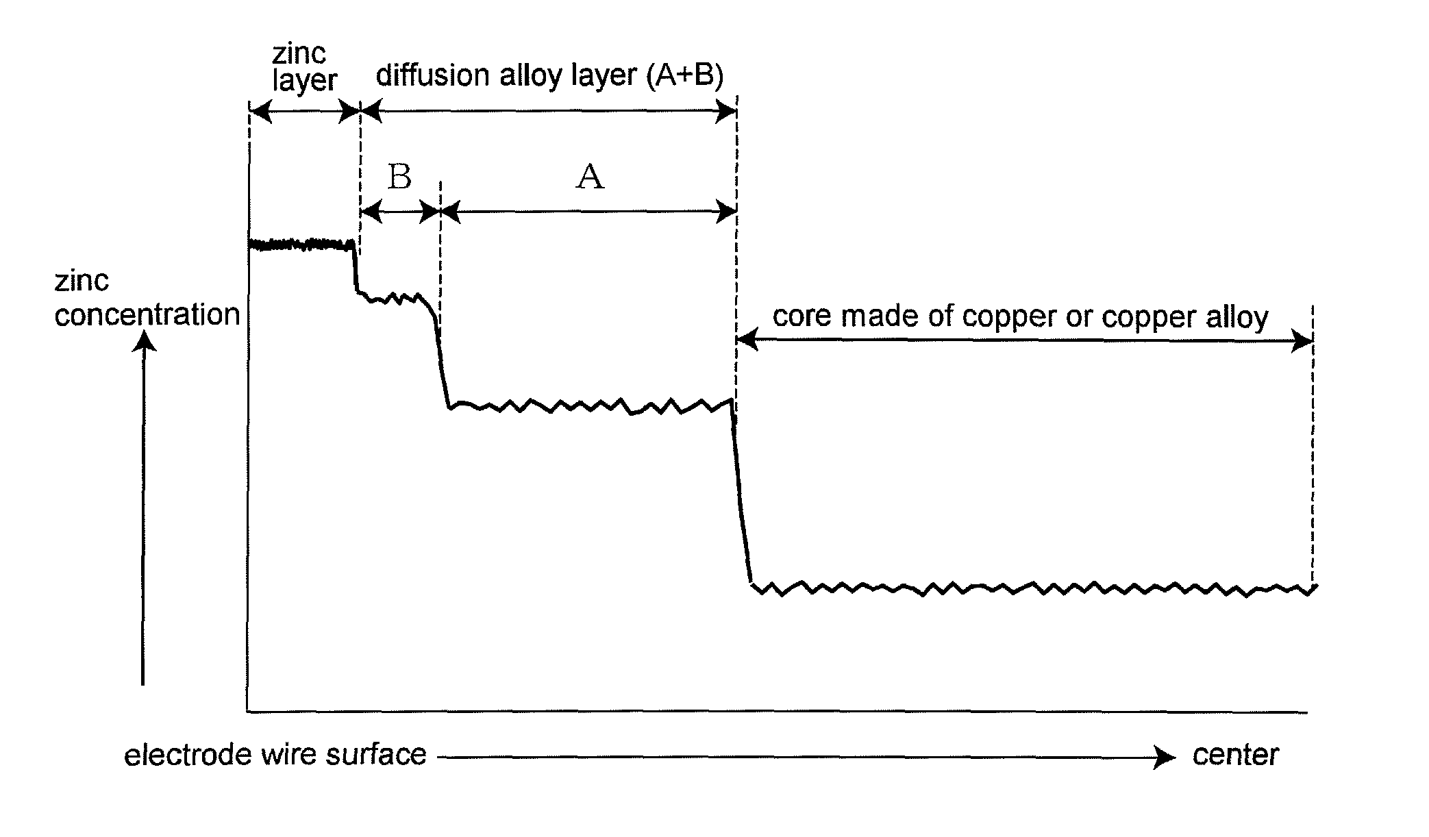
[0085]Controlling the temperature of hot-dip galvanizing and dipping time can determine the thickness of the copper-zinc alloy layer 7, which is a diffusion alloy layer, and the zinc layer 8. The tendencies of thickness variations will be shown below.

1. Diffusion Alloy Layer (Copper-Zinc Alloy Layer)

[0086]a. The diffusion alloy layer becomes thinner when the dipping time is shorter as long as the temperature is the same.

[0087]b. The diffusion alloy layer becomes thinner when the temperature is lower as long as the dipping t...


PUM

PropertyMeasurementUnit
temperatureaaaaaaaaaa
diameteraaaaaaaaaa
temperatureaaaaaaaaaa

Abstract

A wire material having a copper-zinc alloy layer, which is formed by action of thermal diffusion, and a zinc layer on its circumference surface is subjected to processes, including from a step of drawing the wire material to a step of reducing the diameter of the product, to reliably crash the copper-zinc alloy layer into particles. The particles are embedded in the circumference surface of a core to integrate the diffusion alloy layer and zinc layer with the core and prevent the diffusion alloy layer and zinc layer from falling off from the core. In addition, in order to cover cracks formed in the copper-zinc alloy layer during wire drawing with a zinc thin film, wire drawing is performed at temperatures appropriate for maintaining good malleability and ductility of zinc.

Description

CROSS REFERENCE TO RELATED APPLICATION[0001]This application is a continuation of International application No. PCT / JP2011 / 050072, filed Jan. 6, 2011, the contents of which are incorporated herein by reference.[0002]The present application is based on and claims priority of Japanese patent application No. 2010-020826 filed on Feb. 2, 2010, and Japanese patent application No. 2010-175130 filed on Aug. 4, 2010, the entire contents of which are hereby incorporated by reference.BACKGROUND OF THE INVENTION[0003]1. Field of the Invention[0004]The present invention relates to an electrode wire for wire electrical discharge machining that machines a workpiece (an object being machined) with electrical discharges and a method for manufacturing the electrode wire and a method for electrical discharge machining with the electrode wire.[0005]2. Description of the Related Art[0006]The wire electrical discharge machining is used to cut a workpiece by means of heat energy produced by electrical di...

Claims


Application Information

Patent Timeline
Patent Type & Authority Patents(United States)
IPC IPC(8): B23H7/08B23H1/06B23H1/04
CPCB21C1/003B23H7/08B21C9/00Y10T428/12903
Inventor HASHIZUME, KOICHIYOSHIMOTO, MASAKAZUWASHIO, NOBUYUKIKIMOTO, YOICHIROSATO, HIROSHIIZUI, ISAO
Owner OKI ELECTRICAL CABLE
Why Eureka
Try Eureka