Systems and methods for peak-seeking control

a technology of peak-seeking control and system, applied in the field of control systems, can solve the problems of not being able not being able to measure the independent parameters of the performance function, and being unable to provide accurate models in applications

Inactive Publication Date: 2013-05-21
UNIVERSTIY OF CALIFORNIA
View PDF37 Cites 16 Cited by
  • Summary
  • Abstract
  • Description
  • Claims
  • Application Information

AI Technical Summary

Benefits of technology

[0021]It is, therefore, an object of the present invention to provide a more efficient adaptive system and method for peak-seeking control based on measurements of both the independent and dependent parameters of the performance-function.

Problems solved by technology

For example, the mass of an aircraft will decrease in flight as a result of fuel consumption.
These and other MPCs rely on a priori information about time-varying parameters and / or a software model and it is consequently not possible for them to provide an accurate model in applications where a priori information does not exist or is not timely available.
However, there is no provision for measuring the independent parameters of the performance function, nor any algorithm for estimating the vortex or controlling the trailing vehicle to optimize its position relative to the vortex.

Method used


Image

  • Systems and methods for peak-seeking control
  • Systems and methods for peak-seeking control
  • Systems and methods for peak-seeking control

Examples


example # 1

Example #1

Simple One-Input One-Ouput Problem

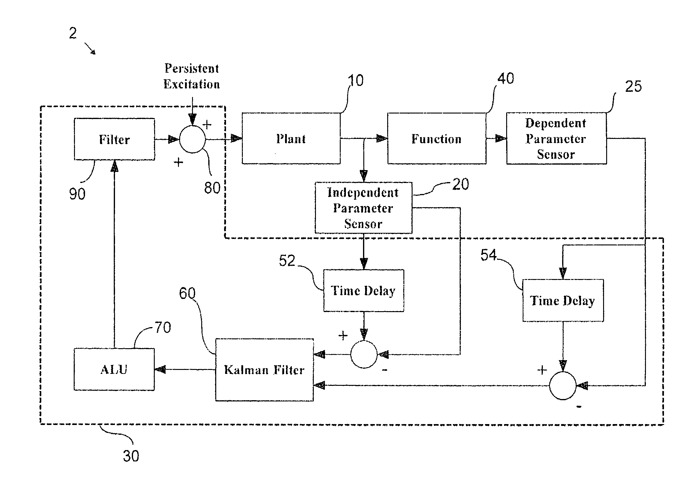
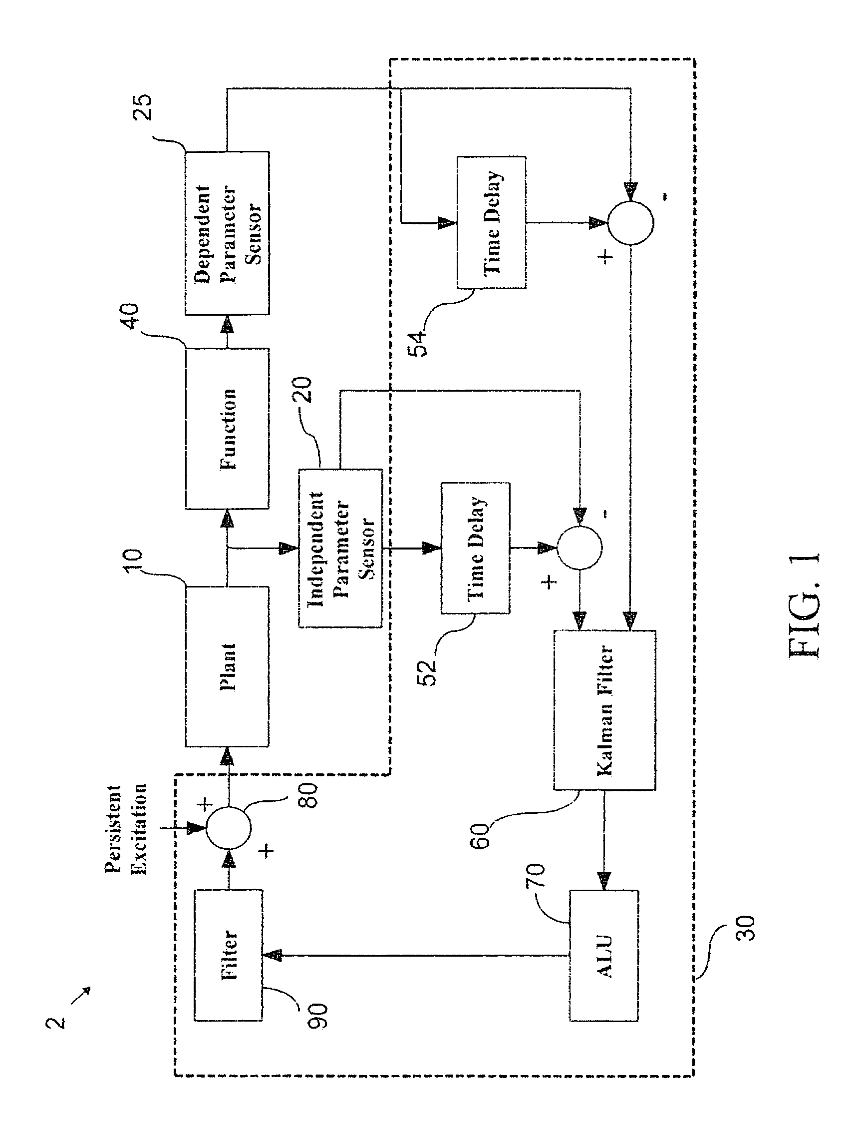
[0065]The following is a one-dimensional example of the method described above. The peak-seeking controller operates on the signals (z, x, y) and ensures that x(t) converges to xmin(θ*). The system under consideration is described by

y=Ay+Bu+; y(0)=yo

x=Cy

z=F(x:θ*)

The continuous linear plant model is given by:

[0066]A=[⁢010001-5-9-5⁢]⁢⁢B=[⁢001⁢]⁢⁢C=[1⁢⁢0⁢⁢0⁢]

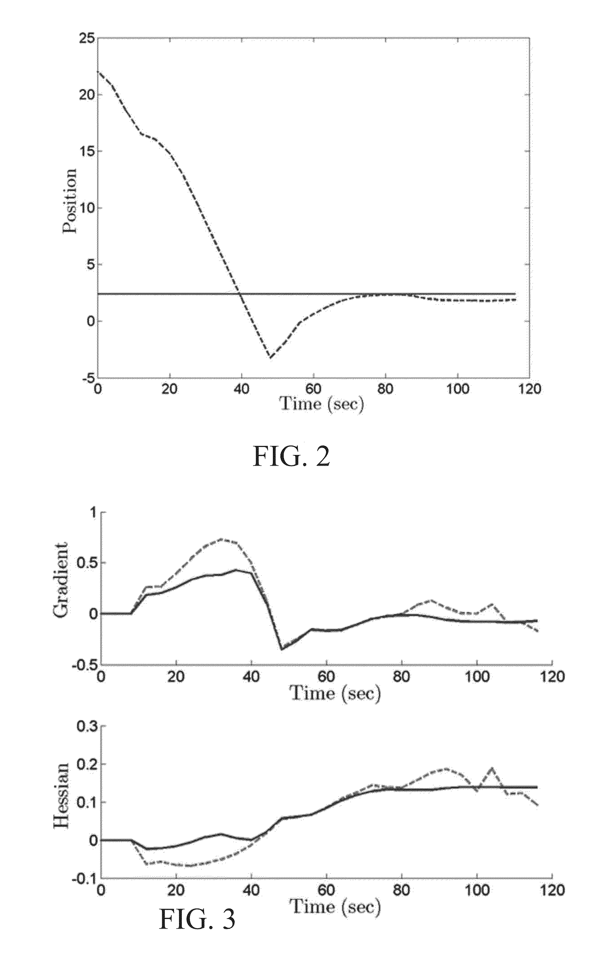
The foregoing system is described in more detail in F. Najson and J. Speyer, “Extremum seeking loop for a class of performance functions,” 15th IFAC World Congress on Automatic Control, Barcelona, Spain, July 2002. For present purposes the performance function is chosen to be f(x)=(cos(x / 8.4)+1.5) (x / 6−0.4)2. Note that this performance function provides a gradient and Hessian that change as a function of position. The performance function magnitude measurements were corrupted with Gaussian distributed noise with a standard deviation of 0.1. There was no noise on the position measurements....

example # 2

Example #2

Two-Input One-Ouput Problem

[0068]A two-dimensional example is presented, and this is more suitable for veicle control in the context of a two-aircraft formation in which the peak-seeking control system 2 is adapted to minimize drag (this is a known application, See, D. F. Chichka et al., supra). It is assumed that a lead aircraft flies in a straight-and-level path. This allows the vortex generated by the lead aircraft to be modeled as static maps of induced drag coefficient and rolling moment on a trailing aircraft as a function of lateral and vertical relative position. The induced drag coefficient map is used as the performance function 40 for plant 60. The magnitude of the rolling moment map for any given position is used as a disturbance input to the trailing aircraft model. The maps were generated using a vortex-lattice method with the trailing aircraft wingtip positioned inside the leading aircraft wingtip vortex. For each position of the map, the aircraft was first ...


PUM


Abstract

A computerized system and method for peak-seeking-control that uses a unique Kalman filter design to optimize a control loop, in real time, to either maximize or minimize a performance function of a physical object (“plant”). The system and method achieves more accurate and efficient peak-seeking-control by using a time-varying Kalman filter to estimate both the performance function gradient (slope) and Hessian (curvature) based on direct position measurements of the plant, and does not rely upon modeling the plant response to persistent excitation. The system and method can be naturally applied in various applications in which plant performance functions have multiple independent parameters, and it does not depend upon frequency separation to distinguish between system dimensions.

Description

CROSS-REFERENCE TO RELATED APPLICATIONS[0001]The present application claims priority to U.S. provisional patent application Ser. No. 61 / 499,249 filed on 21 Jun. 2011, which is incorporated herein by reference.STATEMENT OF GOVERNMENT INTEREST[0002]The invention described hereunder was made in the performance of work under a NASA contract, and is subject to the provisions of Public Law #96-517 (35 U.S.C. 202) in which the Contractor has elected not to retain title.BACKGROUND[0003]a. Field of Invention[0004]The invention relates to control systems suitable for use in a wide variety of applications and, more particularly, to a control system for controlling a physical object as a function of its movement.[0005]b. Background of the Invention[0006]Adaptive control is a technique in which a controller adapts to a controlled system having parameters that vary or are uncertain. For example, the mass of an aircraft will decrease in flight as a result of fuel consumption. An adaptive flight co...

Claims


Application Information

Patent Timeline
Patent Type & Authority Patents(United States)
IPC IPC(8): G05B19/042G06F17/00
CPCG05B13/042
Inventor RYAN, JOHN JSPEYER, JASON L
Owner UNIVERSTIY OF CALIFORNIA
Why Eureka
Try Eureka