
Sound generator for use in parametric array

a sound generator and parametric array technology, applied in the field of sound generators, can solve the problems of reducing the travel distance of the sound wave, requiring high cost for manufacturing a transducer, and requiring large power consumption, and achieve the effect of efficient incorporation of the parametric array mechanism

Inactive Publication Date: 2013-05-28
MOON WONKYU
View PDF6 Cites 2 Cited by
  • Summary
  • Abstract
  • Description
  • Claims
  • Application Information

AI Technical Summary

Benefits of technology

The invention is about a sound generator that can efficiently create sound waves using a single transducer. This allows for the creation of a periodic array of sound waves with a simple structure and can improve the directionality of sound waves with low power. The technical effect of this invention is that it provides a cost-effective and efficient way to create sonic waves with high directivity.

Problems solved by technology

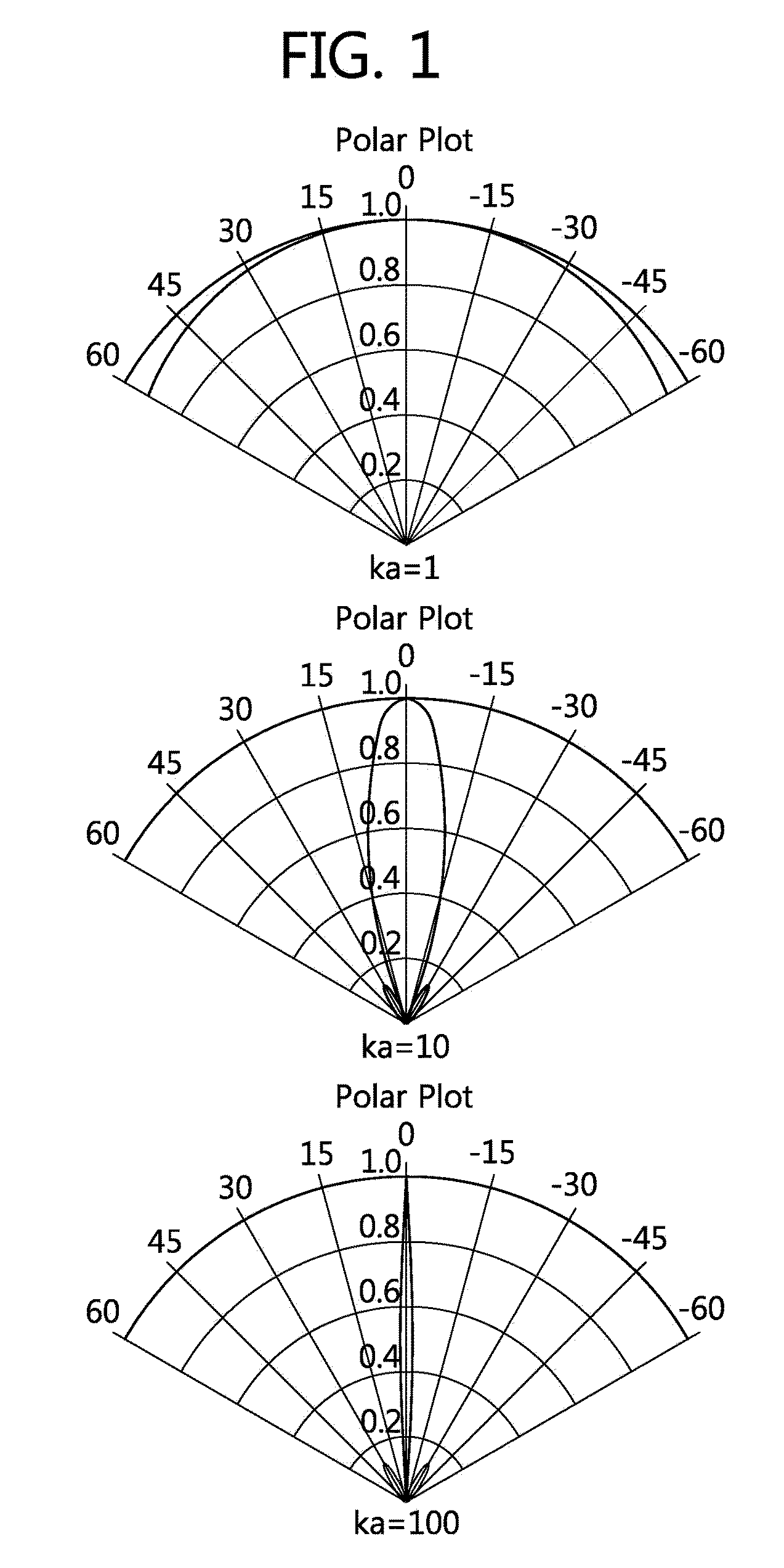
However, when the frequency is raised to secure the high directivity, the traveling distance of the sound wave is shortened due to a high attenuation effect.
However, this method requires much cost for manufacturing a transducer and requires great power consumption.
It can be seen from FIG. 3 that the radiation characteristic of a non-stepped radiation plate due to a distorted vibration is poor.
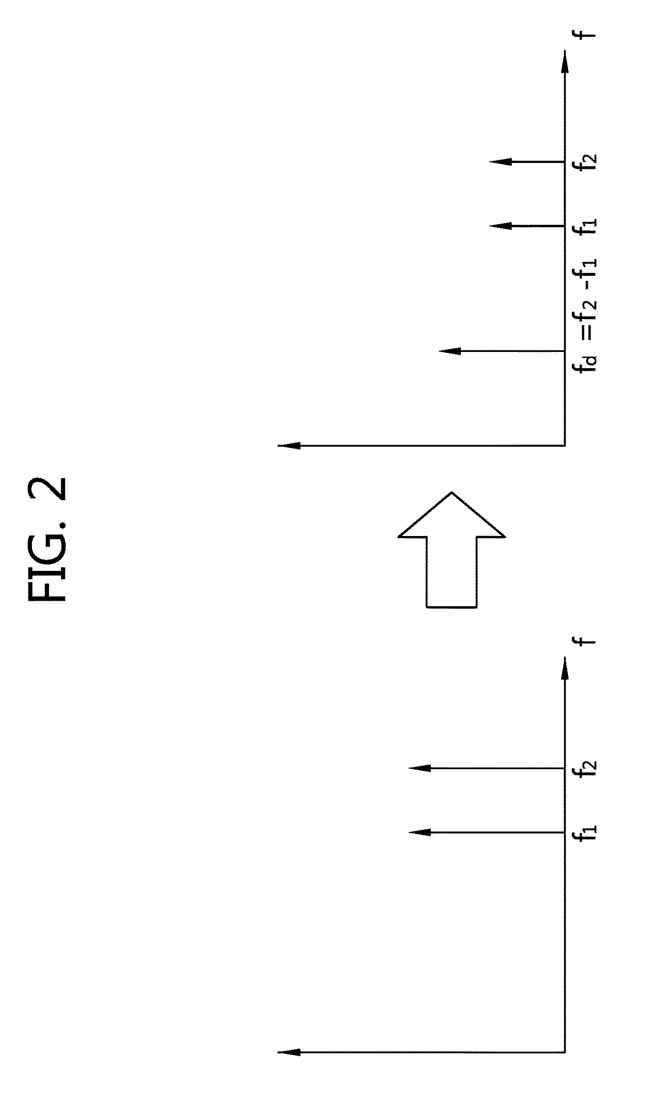
However, since high-pressure sound waves at two or more frequencies are necessary to cause the parametric array mechanism, it is difficult to apply the stepped transducer for the parametric array mechanism.
The ultrasonic distance sensor has a defect that the spatial resolution is small due to the great directivity angle.
However, the array transducer has a problem that much cost and great power consumption are required to manufacture the unit transducers.

Method used


Image

  • Sound generator for use in parametric array
  • Sound generator for use in parametric array
  • Sound generator for use in parametric array

Examples


Embodiment Construction

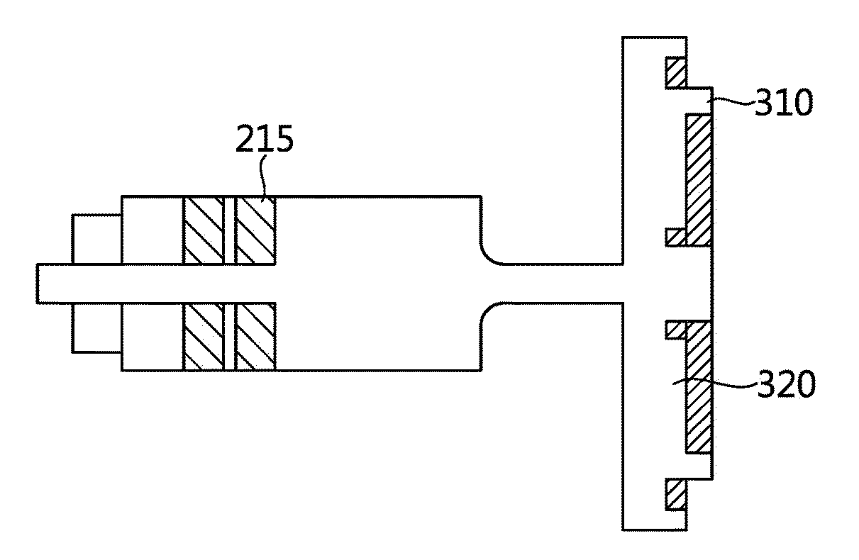
[0033]FIG. 6 is a diagram illustrating the configuration of a sound generation driving system according to an embodiment of the invention. FIG. 7 is a diagram illustrating the structure of a sound generator according to an embodiment of the invention.

[0034]Referring to FIGS. 6 and 7, the sound generation driving system 100 includes a signal generator 110, a signal amplifier 120, and a sound generator 130. The signal generator 110 modulates a signal for causing the parametric array mechanism. The signal amplifier 120 amplifies the modulated signal and transmits the amplified signal to the sound generator 130. The sound generator 130 converts the amplified signal into sound waves. The sound generation driving system 100 can be called a system for driving a stepped transducer generating sound waves having two resonance frequencies.

[0035]The sound generator 130 includes a transducer 210, a driving material 215, a mechanical amplifier 220, and a radiation plate 230. The transducer 210 co...


PUM


Abstract

A sound generator includes a transducer converting electric energy to mechanical energy, a mechanical amplifier mechanically amplifying a vibration generated in a piezoelectric component of the transducer, and a radiation plate radiating a sound wave from a signal amplified by the mechanical amplifier, wherein the radiation plate includes a first step having a height for compensating for a first resonance frequency and a second step having a height for compensating for a second resonance frequency.

Description

CROSS-REFERENCE TO RELATED APPLICATIONS[0001]This application claims the benefit of priority of U.S. Korean Patent Application No. 10-2008-0071816 filed on Jul. 23, 2008 which is incorporated by reference in its entirety herein.FIELD OF THE INVENTION[0002]The present invention relates to a sound generator, and more particularly, to a sound generator capable of generating high-sound-pressure and high-directivity sound waves in two frequency bands to cause an airborne parametric array mechanism.[0003]The invention can be applied to devices requiring two high-power directional sound waves, such as an ultrasonic distance sensor based on a parametric array.[0004]The invention can be also applied to an ultrasonic distance-sensing transducer based on a parametric array.DESCRIPTION OF THE RELATED ART[0005]In general, the directivity of a sound wave generated from a sound generator is expressed as a function of the frequency k and the size of a radiation plate a. As shown in FIG. 1, as the f...

Claims


Application Information

Patent Timeline
Patent Type & Authority Patents(United States)
IPC IPC(8): H04R3/00
CPCB06B3/00G10K13/00H04B13/02H04B13/00
Inventor MOON, WON KYULEE, HAKSUEJE, YUB
Owner MOON WONKYU
Learn More