
Independent variable blade pitch and geometry wind turbine

a technology of variable blade pitch and wind turbine, applied in the direction of wind turbines, machines/engines, wind energy generation, etc., can solve the problems of large windmill-type structures, low efficiency rates, and inability to adjust, so as to increase the adaptability of the wind turbine to the wind conditions, increase the electrical output and efficiency, and increase the ability to harness the wind energy

Inactive Publication Date: 2013-06-04
ELKIN BENJAMIN T +1
View PDF9 Cites 8 Cited by
  • Summary
  • Abstract
  • Description
  • Claims
  • Application Information

AI Technical Summary

Benefits of technology

This patent describes a wind turbine design that improves its ability to adapt to different wind conditions. The design has separate sections for the rotor blades and the support, which can rotate through predetermined ranges to optimize the turbine's performance. Additionally, the first rotor blades are shorter than the blades on the downwind second rotor blades, which allows for better utilization of wind energy and increased efficiency of the turbine.

Problems solved by technology

There have been challenges and previously proposed solutions for harnessing wind energy through use of electric wind turbines.
These large windmill-type structures suffer from many disadvantages including, the ability to adjust to variable wind conditions in either or both of direction or velocity.
Additional disadvantages of prior wind turbines include relatively low efficiency rates due to standard designs that are employed in environments not suitable for the particular wind turbine design or initial set-up.
Due to the size and mass of large wind turbines, premature structural fatigue and failure of components occur.
Prior wind turbines also suffer from inefficient and complex designs.

Method used


Image

  • Independent variable blade pitch and geometry wind turbine
  • Independent variable blade pitch and geometry wind turbine
  • Independent variable blade pitch and geometry wind turbine

Examples


Embodiment Construction

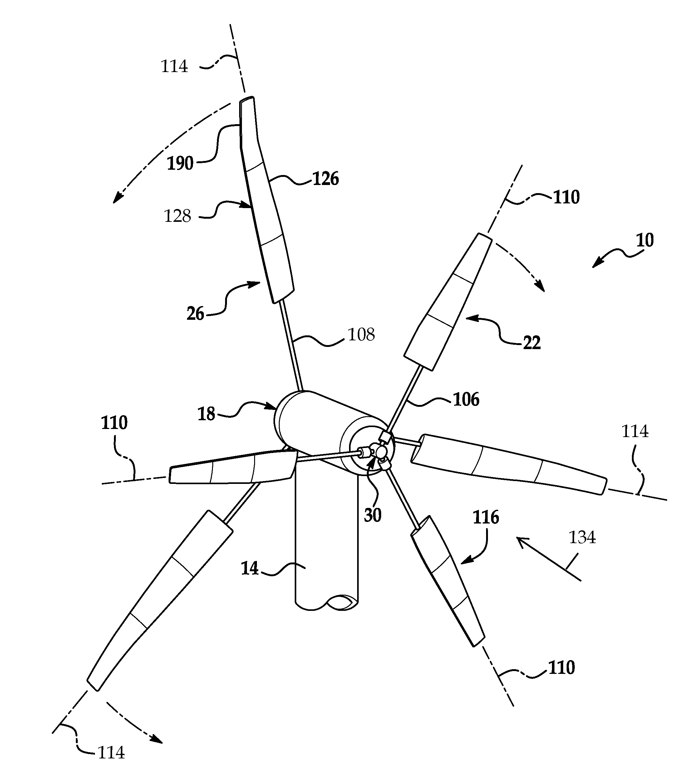
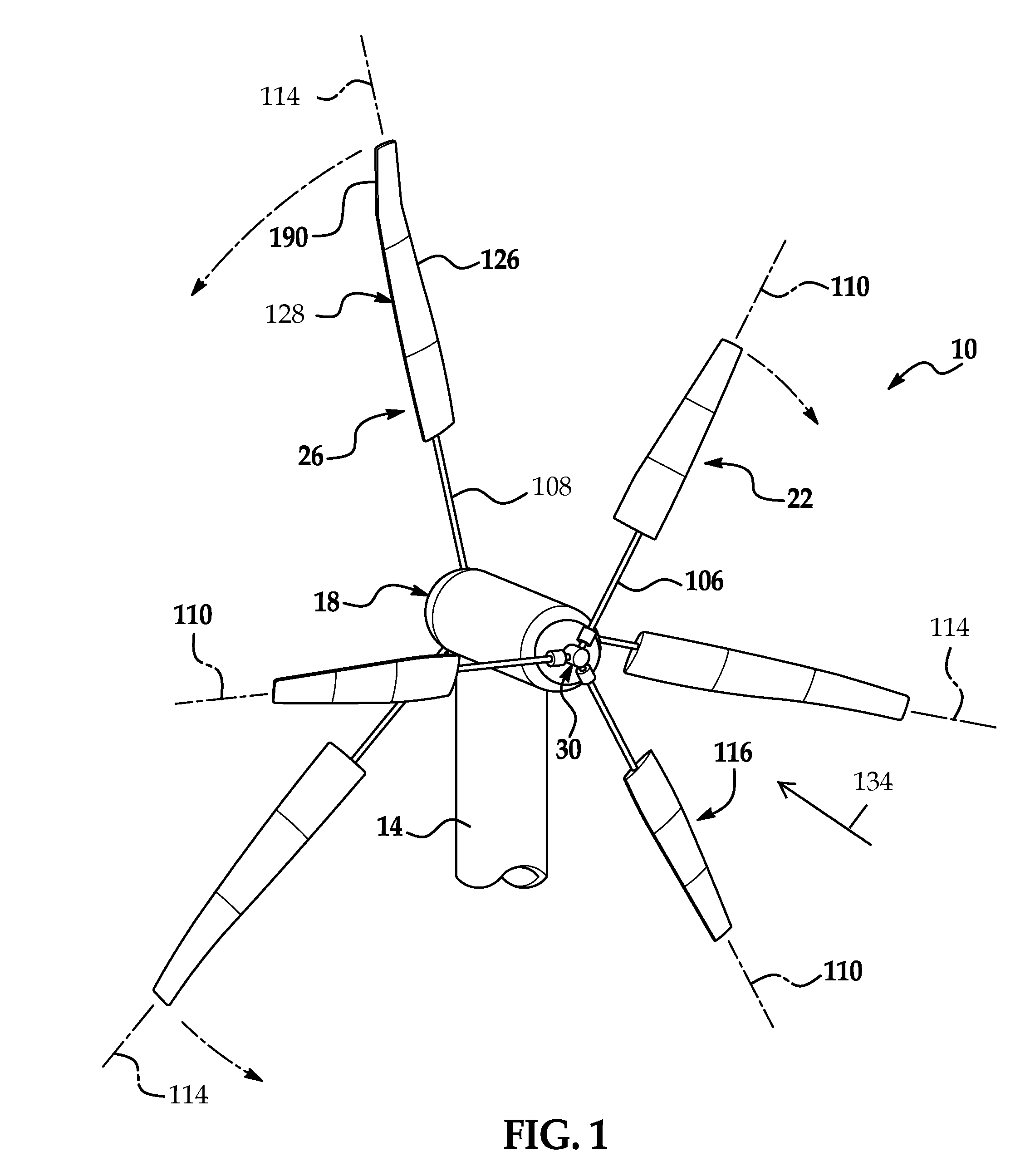
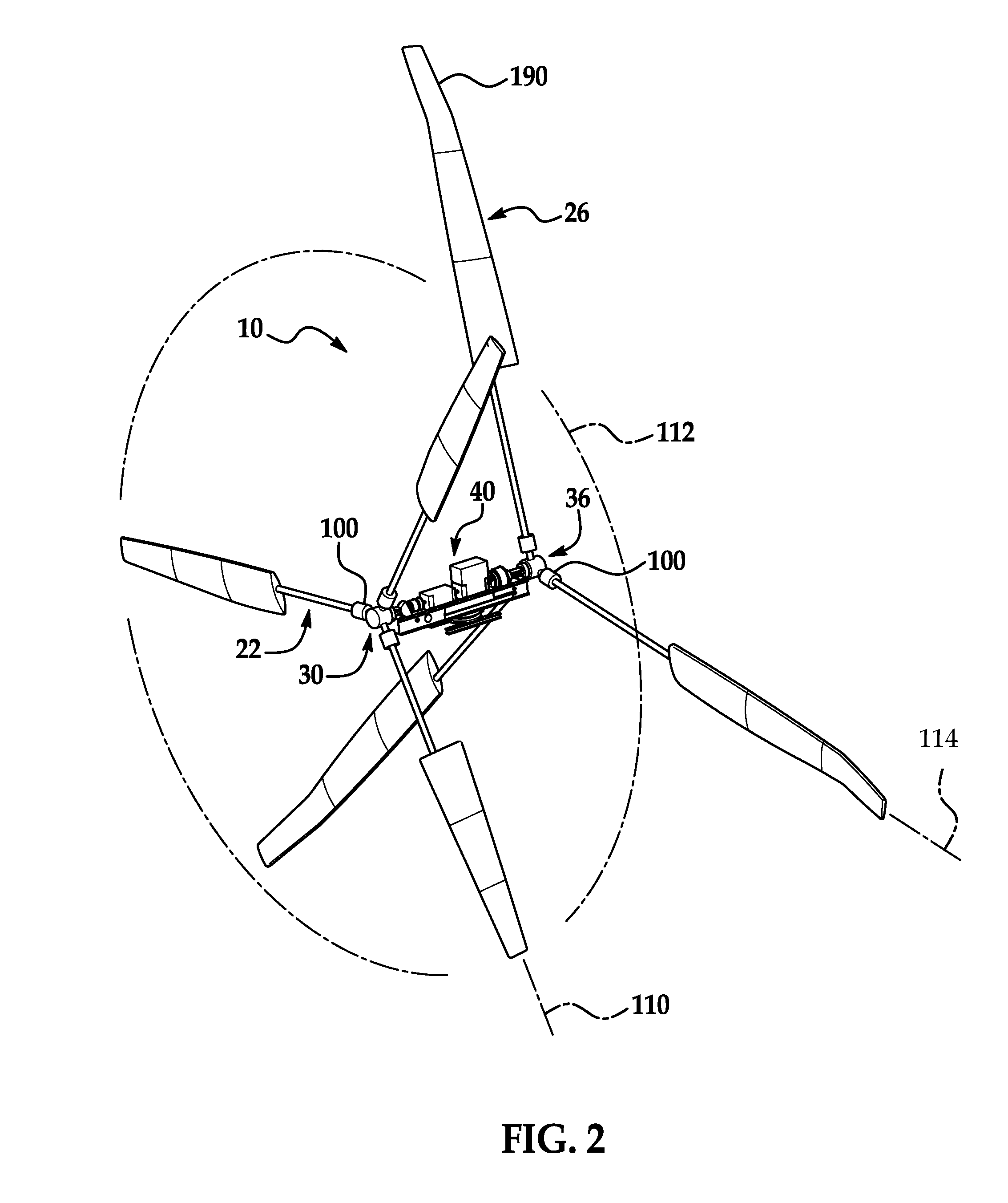
[0020]Examples of an inventive wind turbine 10 are shown in FIGS. 1-6. Referring to FIGS. 1 and 2, a wind turbine 10 includes a tower 14 (partially shown) anchored to a foundation (not shown) secured to the earth by means known to those skilled in the field. Tower 14 is typically 200-300 feet in height depending on the application. Secured to the top of the tower is a nacelle 18 housing power transmission equipment 40 described in further detail below. Although the nacelle 18 is illustrated atop tower 14, it is within the scope of the invention that the nacelle 18 could be mounted to other structures or towers of alternate heights and tower constructions.

[0021]In the example shown in FIGS. 1 and 2, wind turbine 10 includes a front rotor 22 positioned at one end of the nacelle 18 and a rear rotor 26 positioned at the opposite end of the nacelle 18 as generally illustrated. Hereinafter, front rotor 22 is referred to as first rotor 22, and rear rotor 26 is referred to as second rotor 2...


PUM


Abstract

A variable blade pitch wind turbine and method of passively varying the blade pitch is presented. Each blade of the turbine rotor can individually and passively rotate about a respective blade axis to continuously vary the pitch of the blades to adjust to the ever changing wind speed and direction without active controls or other mechanical or electrical induced inputs to force rotational movement of the blades. Sections of each blade can respectively rotate to change the blade twist. In one example, a second rotor is used to increase the electrical generation and efficiency of the blade turbine.

Description

TECHNICAL FIELD[0001]The general field of invention is alternative energy.BACKGROUND[0002]There has long been motivation for alternative energy sources to reduce the dependency on non-renewable energy sources such as oil and coal. There has long been interest in harnessing wind to generate electricity particularly in areas with a high or relatively continuous stream of wind energy.[0003]There have been challenges and previously proposed solutions for harnessing wind energy through use of electric wind turbines. These large windmill-type structures suffer from many disadvantages including, the ability to adjust to variable wind conditions in either or both of direction or velocity. Additional disadvantages of prior wind turbines include relatively low efficiency rates due to standard designs that are employed in environments not suitable for the particular wind turbine design or initial set-up. Due to the size and mass of large wind turbines, premature structural fatigue and failure ...

Claims


Application Information

Patent Timeline
Patent Type & Authority Patents(United States)
IPC IPC(8): F03D1/02F03D7/02
CPCF03D1/025F03D1/0666F03D7/0224F03D7/041F05B2240/30F05B2240/31F05B2270/402Y02E10/721Y02E10/723Y02E10/72F03D1/0658
Inventor ELKIN, BENJAMIN T.ELKIN, BRENT T.
Owner ELKIN BENJAMIN T
Learn More