Fibrous structures comprising a region of auxiliary bonding and methods for making same

a technology of auxiliary bonding and fibrous structure, which is applied in the field of fibrous structure, can solve the problems of fibrous structure, fibrous structure, and dust problems, and achieve the effect of reducing the amount of dust generated

Active Publication Date: 2013-06-04
PROCTER & GAMBLE CO
View PDF75 Cites 6 Cited by
  • Summary
  • Abstract
  • Description
  • Claims
  • Application Information

AI Technical Summary

Benefits of technology

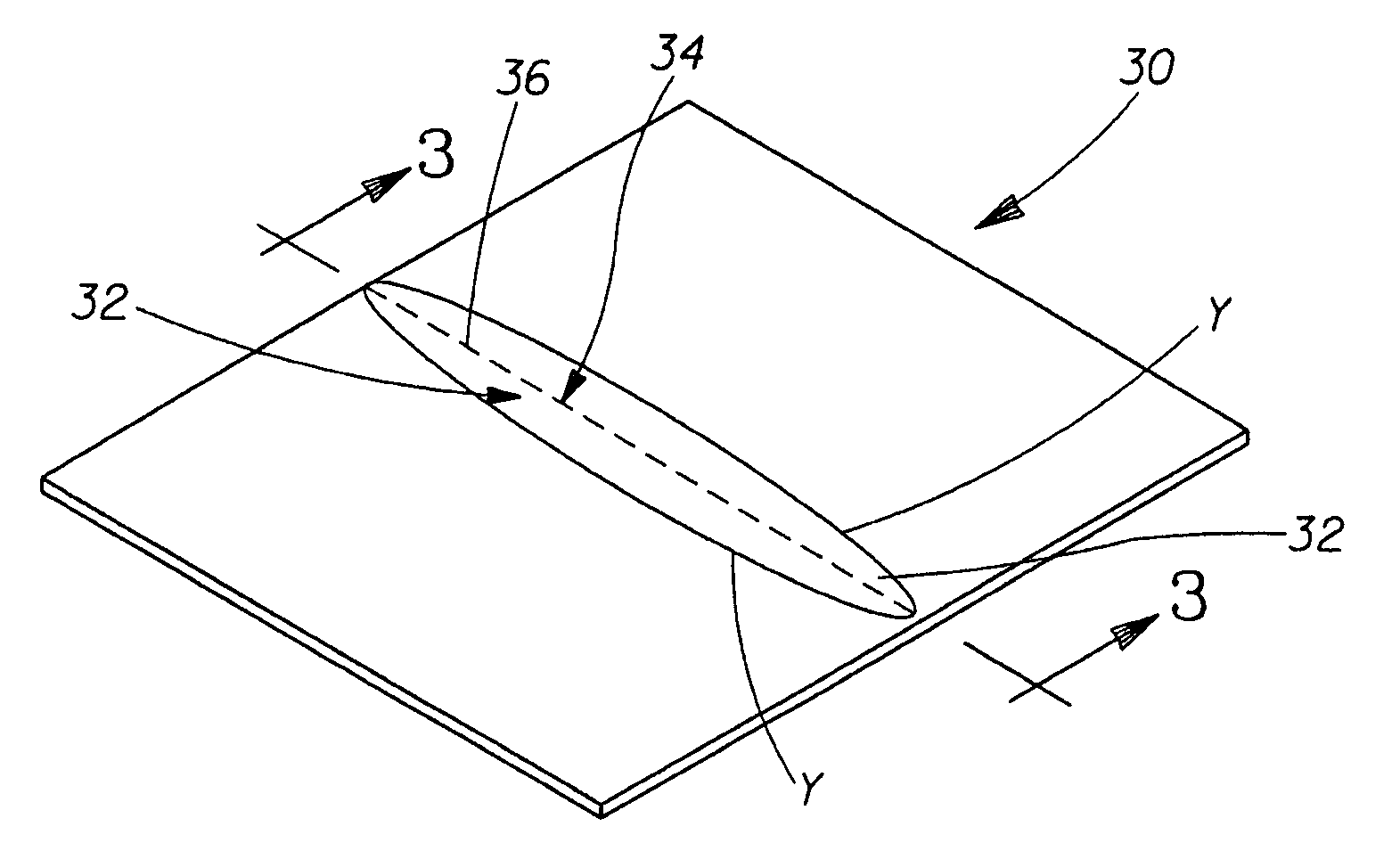
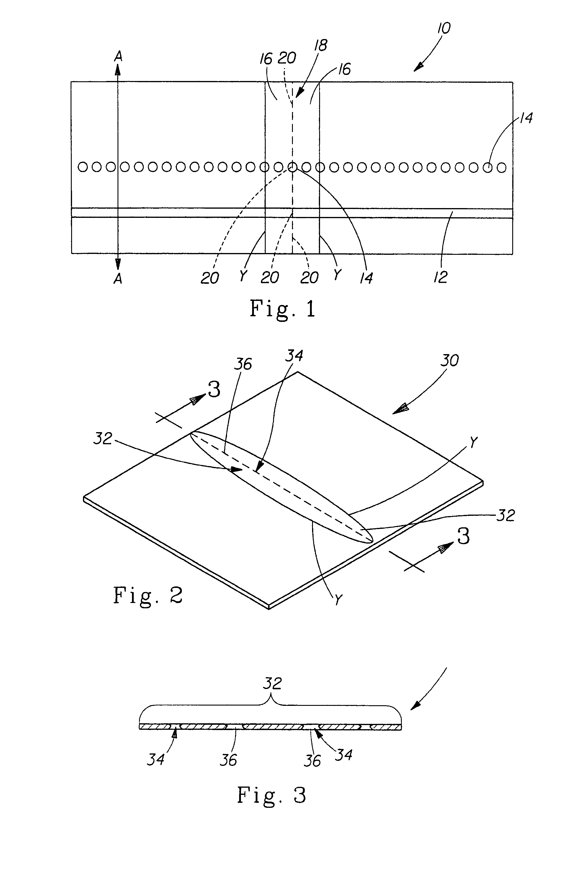
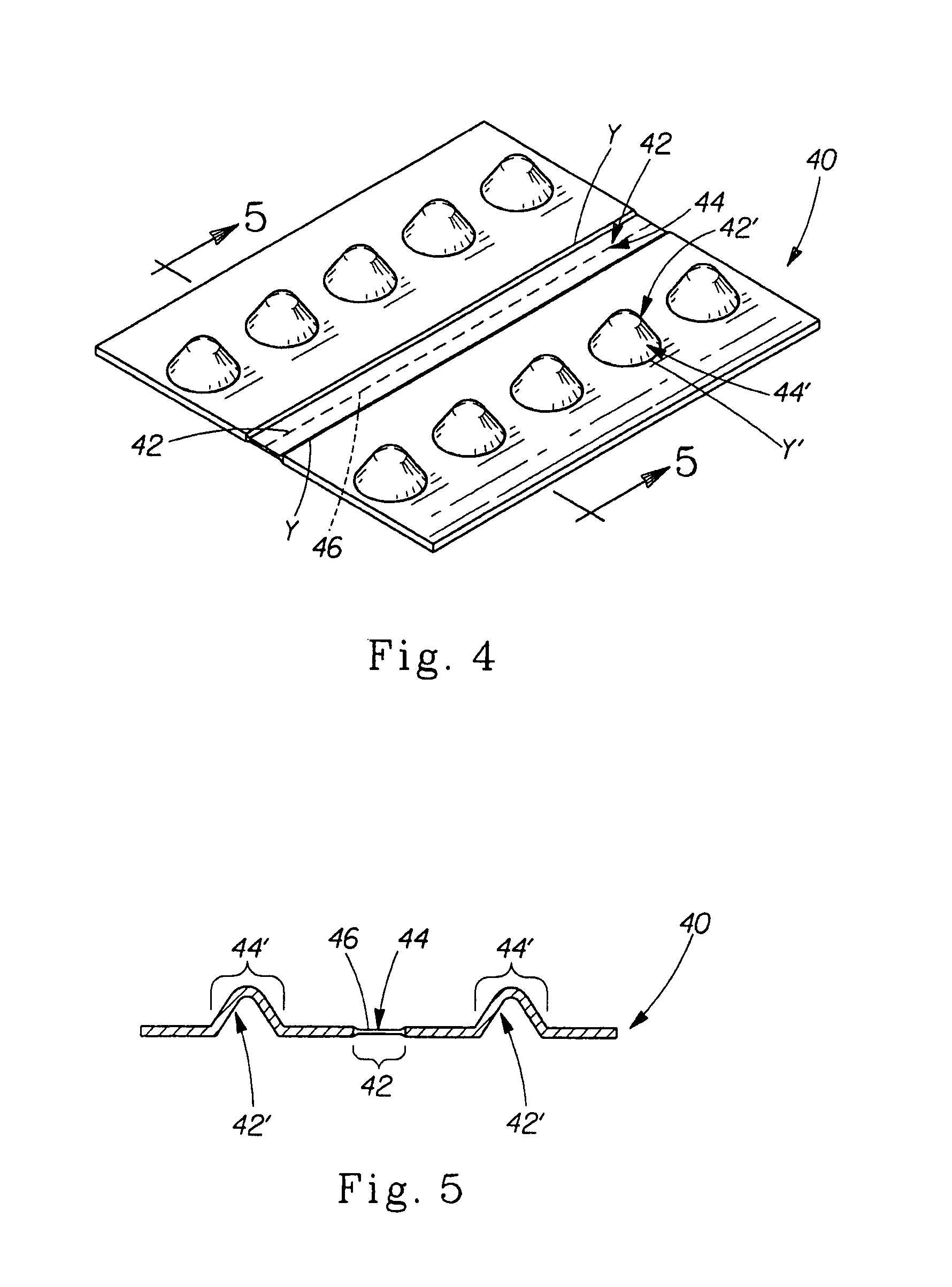
[0006]The present invention fulfills the needs described above by providing a fibrous structure and / or a sanitary tissue product comprising such a fibrous structure that utilizes auxiliary bonding to reduce the dust generated from fibrous structures and / or sanitary tissue products, especially during use by a consumer and a method for making same.
[0010]In yet another example of the present invention, a method for reducing the dust generated by a single-ply fibrous structure and / or single-ply sanitary tissue product, the method comprising the step of imparting a solid state disruption zone and an auxiliary bonding region in the fibrous structure and / or sanitary tissue product, wherein the zone and region at least partially overlap, is provided.
[0011]In even still another example of the present invention, a method for reducing the dust generated by a fibrous structure and / or a sanitary tissue product, the method comprising the step of imparting a region of fiber disruption comprising a dust inhibiting agent in the fibrous structure and / or sanitary tissue product, is provided.
[0013]In yet even another example of the present invention, a fibrous structure is provided which has a dispensing dust value reduced by creating a region of auxiliary bonding wherein the region of auxiliary bonding alters the dispensing dust by decreasing the normalized dispensing dust relative to the fibrous structure without the region of auxiliary bonding, is provided.

Problems solved by technology

Fibrous structures, especially through-air-dried fibrous structures and sanitary tissue products incorporating such fibrous structures, have been plagued with dust problems.
Over the years, formulators have failed to improve the dust problems, especially the dust problems originating from solid state disruption zones.
As a result, consumers continue to be subjected to a cloud of dust from fibrous structures, especially sanitary tissue products, during use, especially when dispensing sheets from a convolutedly wound roll of sanitary tissue product.

Method used


Image

  • Fibrous structures comprising a region of auxiliary bonding and methods for making same
  • Fibrous structures comprising a region of auxiliary bonding and methods for making same
  • Fibrous structures comprising a region of auxiliary bonding and methods for making same

Examples


example 1

[0101]A reference sanitary tissue product is created by making a two ply fibrous structure suitable for converting into toilet tissue by laminating plies of through-air-dried paper fibrous structures on a toilet tissue converting line. Approximately 1″ wide bands of pressure sensitive hot melt adhesive are continuously applied to one of the fibrous structures on 4.5″ centers and the two fibrous structures are passed through a combining nip to laminate them into a two-ply fibrous structure. The combined fibrous structure is perforated into 4″ sheets using perf blades having 99 binding sites (i.e. gaps) each 0.011″±0.001″ wide per 4.5″ roll acting against a rotating anvil roll. The angle of entry of the web path into the perf blade anvil nip is positioned so the web only contacts the anvil roll at the point of minimum clearance between the perf blade and anvil roll. The perforated fibrous structure is then wound into logs on 1.71″ cores until 200 sheets are accumulated on each log. Th...

example 2

[0102]To illustrate one aspect of the present invention, the fibrous structure and sanitary tissue product-making of Example 1 is repeated except a slot extruder is positioned to uniformly coat the anvil roll with STP® oil treatment. STP® oil treatment is a product of Armor All / STP Products Company of Oakland Calif. and is a mineral oil containing an olefin co-polymer which serves to make it a low migration lubricant (an auxiliary bonding agent). As the perf blade contacts the fibrous structure, the fibrous structure is forced down to the anvil roll and the oil is transferred into the fibrous structure covering the solid state disruption zone. The STP® oil treatment is added at approximately 3% by weight. The rolls are stored at room temperature for 6 weeks prior to testing for dispensing dust. At that time the width of the STP® oil treatment across the perfs is ⅜″ wide at maximum migration. Properties of this sanitary tissue product are shown in Table I, below.

[0103]

TABLE IExample ...

example 3

[0104]To illustrate another aspect of the present invention, fibrous structure product logs from Example 1 are conveyed to the log saw to saw 4.5″ wide sanitary toilet tissue product; however at this point the existing oiling mechanism of the PCMC R961 log sawing machine is utilized to deliver auxiliary bonding agent to the cutting blade for deposition to the saw cut area of the sanitary tissue product. The auxiliary bonding agent is a low migration lubricant (STP® oil treatment). It is delivered continuously through the oiling mechanism at a rate sufficient to deposit 3% by weight to the sanitary tissue product. The transfer of the lubricant to the solid state disruption zone (the saw cut) occurs as the blade passes through the log, the lubricant is deposited onto the cut surface. Example 3 is observed to have much lower dust arising from the saw cut solid state disruption zone compared to Example 1.


PUM

PropertyMeasurementUnit
densityaaaaaaaaaa
pressureaaaaaaaaaa
temperatureaaaaaaaaaa

Abstract

Fibrous structures, more particularly fibrous structures comprising a region of auxiliary bonding and methods for making same are provided.

Description

CROSS REFERENCE TO RELATED APPLICATIONS[0001]This application claims the benefit of U.S. Provisional Application No. 60 / 800,725, filed May 16, 2006.FIELD OF THE INVENTION[0002]The present invention relates to fibrous structures, more particularly to fibrous structures comprising a region of auxiliary bonding, especially a region of auxiliary bonding that contains within it a region of fiber disruption, and methods for making same.BACKGROUND OF THE INVENTION[0003]Fibrous structures, especially through-air-dried fibrous structures and sanitary tissue products incorporating such fibrous structures, have been plagued with dust problems. A major source of dust from fibrous structures are regions of fiber disruption, including but not limited to, solid state disruption zones (such as perforated areas, embossed areas, and the like) in the fibrous structure.[0004]Over the years, formulators have failed to improve the dust problems, especially the dust problems originating from solid state d...

Claims


Application Information

Patent Timeline
Patent Type & Authority Patents(United States)
IPC IPC(8): B32B3/10B32B3/24B32B5/26B32B7/14B32B5/02
CPCA47K10/16D21H21/18D21H25/005D21H27/008B26F1/14Y10T428/24777Y10T428/24612Y10T428/2481Y10T428/24479Y10T428/15Y10T428/24992Y10T428/24273Y10T428/24793Y10T428/24802Y10T428/24934Y10T428/24322
Inventor VINSON, KENNETH DOUGLASULLMAN, ALAN HOWARDNOLTING, CHARLES ANDREW
Owner PROCTER & GAMBLE CO
Why Eureka
Try Eureka