Printing apparatus

a printing apparatus and printing technology, applied in the field of printing apparatuses, can solve the problems of unnecessarily long power-off time and the longer period of time required to print a predetermined number of lines, and achieve the effect of shortening the overall printing time and shortening the life of the heating resistance elemen

Inactive Publication Date: 2013-06-04
SEIKO INSTR INC
View PDF4 Cites 2 Cited by
  • Summary
  • Abstract
  • Description
  • Claims
  • Application Information

AI Technical Summary

Benefits of technology

[0007]The present invention has been made in view of the above-mentioned problem, and it is therefore an object of the present invention to provide a printing apparatus capable of shortening an overall printing time without shortening a life of a heating resistance element of a thermal head.
[0009]In the printing apparatus, the printing control unit may shorten the power-off time as the detected voltage becomes lower.
[0012]According to the present invention, when the voltage is low, it is possible to shorten the overall printing time without shortening the life of the heating resistance element of the thermal head.

Problems solved by technology

Therefore, when the power supply voltage is low, the power-off time is unnecessarily long even though a shorter power-off time suffices as compared to the case where the power supply voltage is high.
Thus, there is a problem in that, when the voltage is low, it takes a longer period of time to print a predetermined number of lines (hereinafter, referred to as “overall printing time”).

Method used


Image

  • Printing apparatus
  • Printing apparatus
  • Printing apparatus

Examples


Embodiment Construction

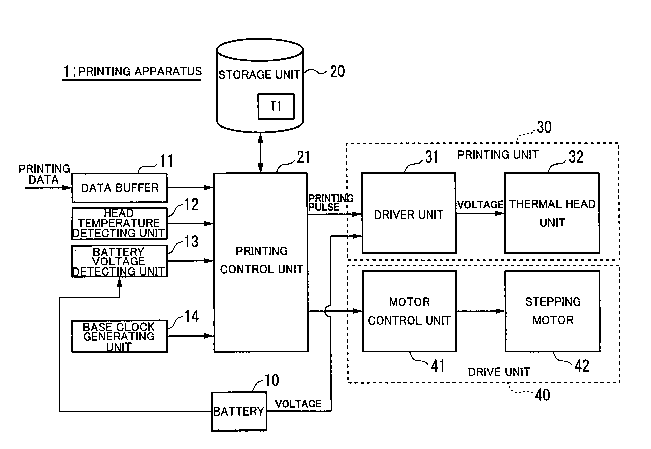
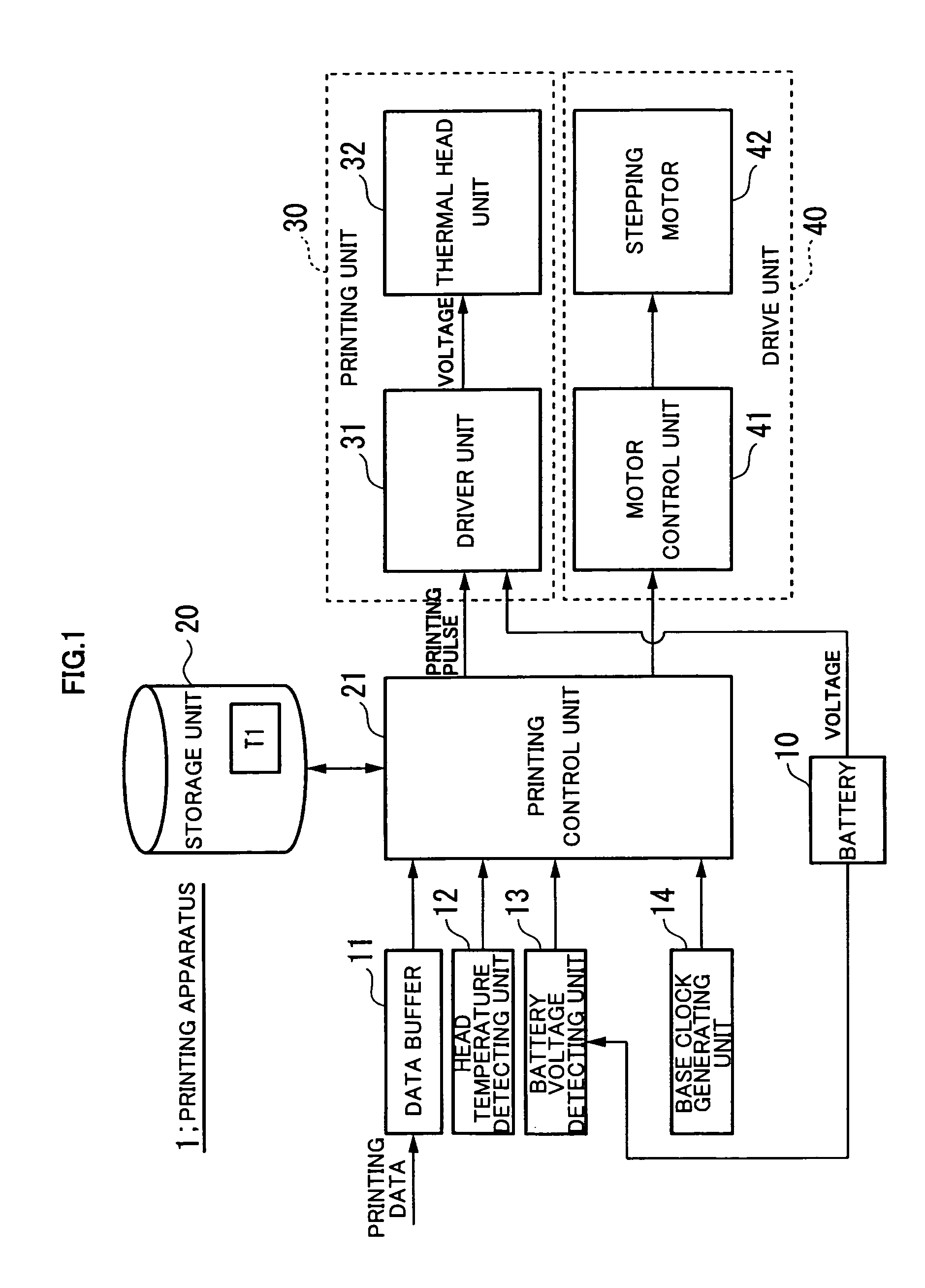
[0020]Hereinbelow, an embodiment of the present invention is described in detail with reference to the accompanying drawings. FIG. 1 is a block configuration diagram of a printing apparatus 1 according to the embodiment of the present invention. The printing apparatus 1 includes a battery (power source unit) 10, a data buffer 11, a head temperature detecting unit 12, a battery voltage detecting unit (voltage detecting unit) 13, a base clock generating unit 14, a storage unit 20, a printing control unit 21, a printing unit 30, and a drive unit 40.

[0021]Further, the printing unit 30 includes a driver unit 31 and a thermal head unit 32. The drive unit 40 includes a motor control unit 41 and a stepping motor 42.

[0022]The battery 10 supplies a voltage to the driver unit 31 of the printing unit 30.

[0023]In the data buffer 11, printing data input from a printing data providing apparatus (not shown) is accumulated.

[0024]The head temperature detecting unit 12 detects the temperature of the t...


PUM


Abstract

A printing apparatus includes a printing unit for performing printing by pressing a thermal head onto heat sensitive paper to heat the heat sensitive paper. A battery supplies a voltage to the thermal head, and a battery voltage detecting unit detects the voltage. A printing control unit changes, according to the detected voltage, a power-off time in which power supply from the battery to the thermal head is stopped. The printing control unit calculates the power-off time based on the detected voltage and the resistance of the thermal head and shortens the power-off time as the detected voltage becomes lower thereby shortening the overall printing time without shortening the life of the heating resistance elements of the thermal head.

Description

BACKGROUND OF THE INVENTION[0001]1. Field of the Invention[0002]The present invention relates to a printing apparatus.[0003]2. Description of the Related Art[0004]In a thermal printer, when power is successively supplied to a heating resistance element of a certain thermal head, there is provided a power-off time, in which the power supply is stopped, between a power-on time in which power is supplied to the heating resistance element for printing one-line data and a power-on time in which power is supplied to the heating resistance element for printing succeeding one-line data. The power-off time is provided for the purpose of avoiding a trailing phenomenon, and further, attaining a longer life of the heating resistance element of the thermal head (see, for example, Japanese Patent Application Laid-open No. Hei 5-345437).[0005]Conventionally, the power-off time in which the power supply is stopped is set so as not to shorten the life of the heating resistance element of the thermal...

Claims


Application Information

Patent Timeline
Patent Type & Authority Patents(United States)
IPC IPC(8): B41J2/35B41J2/365B41J2/37
CPCB41J2/355
Inventor SHOJI, NORIYOSHIOGURA, TOMOKIMIYAWAKI, KOUHEISANBONGI, NORIMITSU
Owner SEIKO INSTR INC
Why Eureka
Try Eureka