Hole positioning system

Inactive Publication Date: 2013-06-11
SCHMITT ARTHUR REX
View PDF27 Cites 15 Cited by
  • Summary
  • Abstract
  • Description
  • Claims
  • Application Information

AI Technical Summary

Benefits of technology

The invention is a device for drilling holes in cabinet panels that provides small-shop cabinet manufacturers with a fast, economical, and compact way to do so. It allows for greater precision and a faster rate of drilling compared to previous methods, such as manual systems or lower-cost multi-spindle drill equipment. The device can be easily stored when not in use by hanging it from a wall or leaning it against a wall.

Problems solved by technology

In larger cabinet shops or furniture factories these 5 mm hardware mounting holes are often drilled on large expensive multi spindle drill machines or on even more large and expensive computer controlled panel processing machines and point to point drilling machines.
A great deal of floor space and capital investment are required.
Unfortunately these jigs, templates etc. are sometimes inaccurate in locating holes, slow to set up, often locate and drill only a small number of holes per set up, require substantial time resetting for subsequent columns or rows of holes.
Some systems require considerable effort and accumulated time to lift a router off a template or a drill from a guide bushing then reinserting it for each hole to be drilled.
Unfortunately portable drills tend to produce imperfect holes with chipped edges or torn veneer.
U.S. Pat. No. 5,560,408 uses a clamp on template and a plunge router with a guide bushing to drill columns of holes for shelf supports but would not work well to drill holes at specific spacings to fit the screw holes in the front and back ends of drawer slides.
U.S. Pat. No. 5,217,331 likewise designed to drill holes for shelf supports would not work well for drawer slide screws.
Productivity issues and the appearance and precision of the holes are a real concern.
Drilling with an inefficient system requiring frequent resetting or repositioning of jigs or fixtures, and or the lifting of a plunge router or hand drill and realigning and reinserting of a bit or guide bushing into a template or drill guide for each hole would be extremely tedious.
Generally the systems described here as prior art are not best suited for the uniform high quality production drilling required in a small commercial shop.

Method used


Image

  • Hole positioning system
  • Hole positioning system
  • Hole positioning system

Examples


Embodiment Construction

[0040]Note: The first 4 paragraphs following this note, with only a few reference numbers, provide additional familiarization with the invention while paragraph five begins a detailed description of components, manufacture, and sequence of operations for the invention.

[0041]The invention described here as the “preferred embodiment” is sized and laid out in a way that is believed by the inventor to be its most productive configuration for use in cabinet manufacturing. It could be produced in ways that would be less costly to build. Some of those ways will be discussed later in this section.

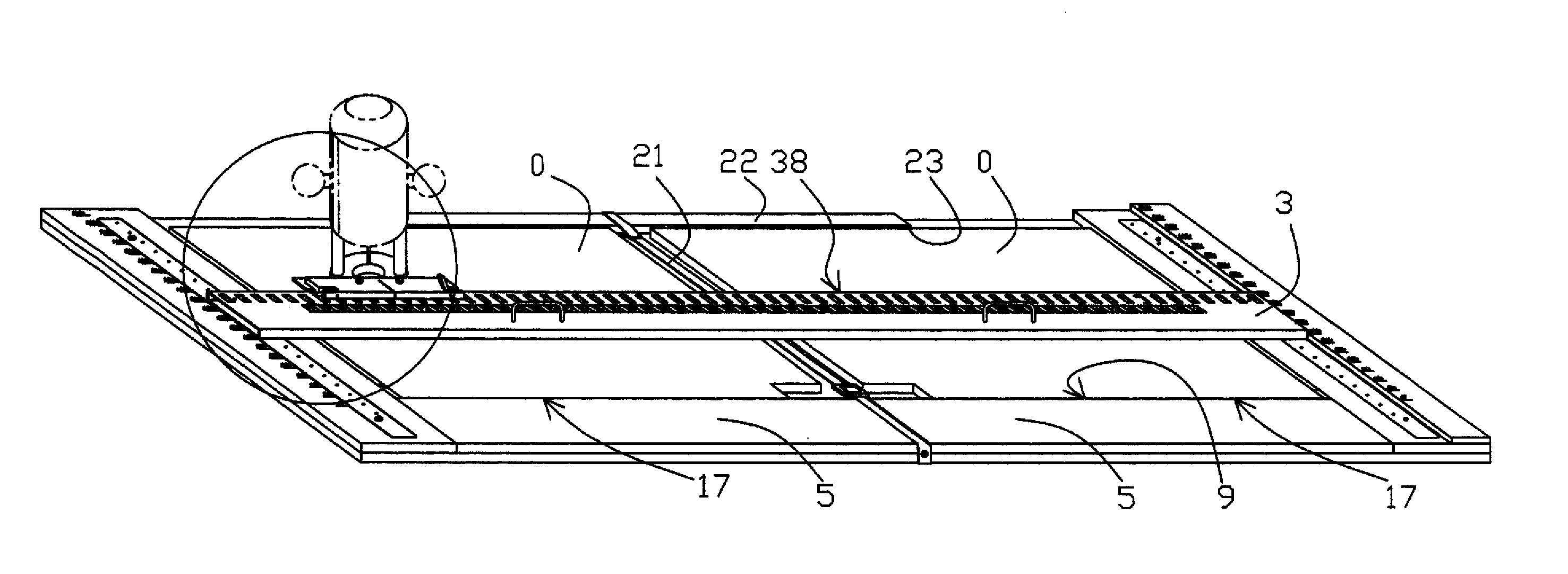
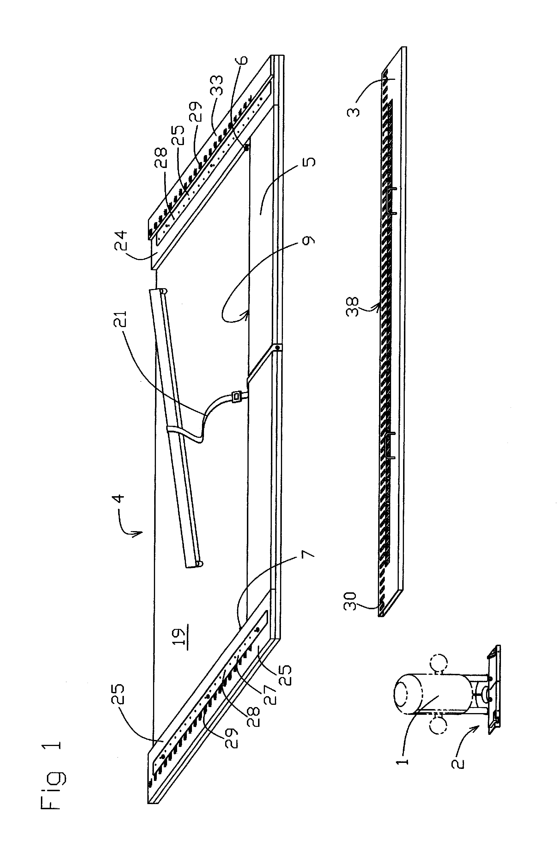
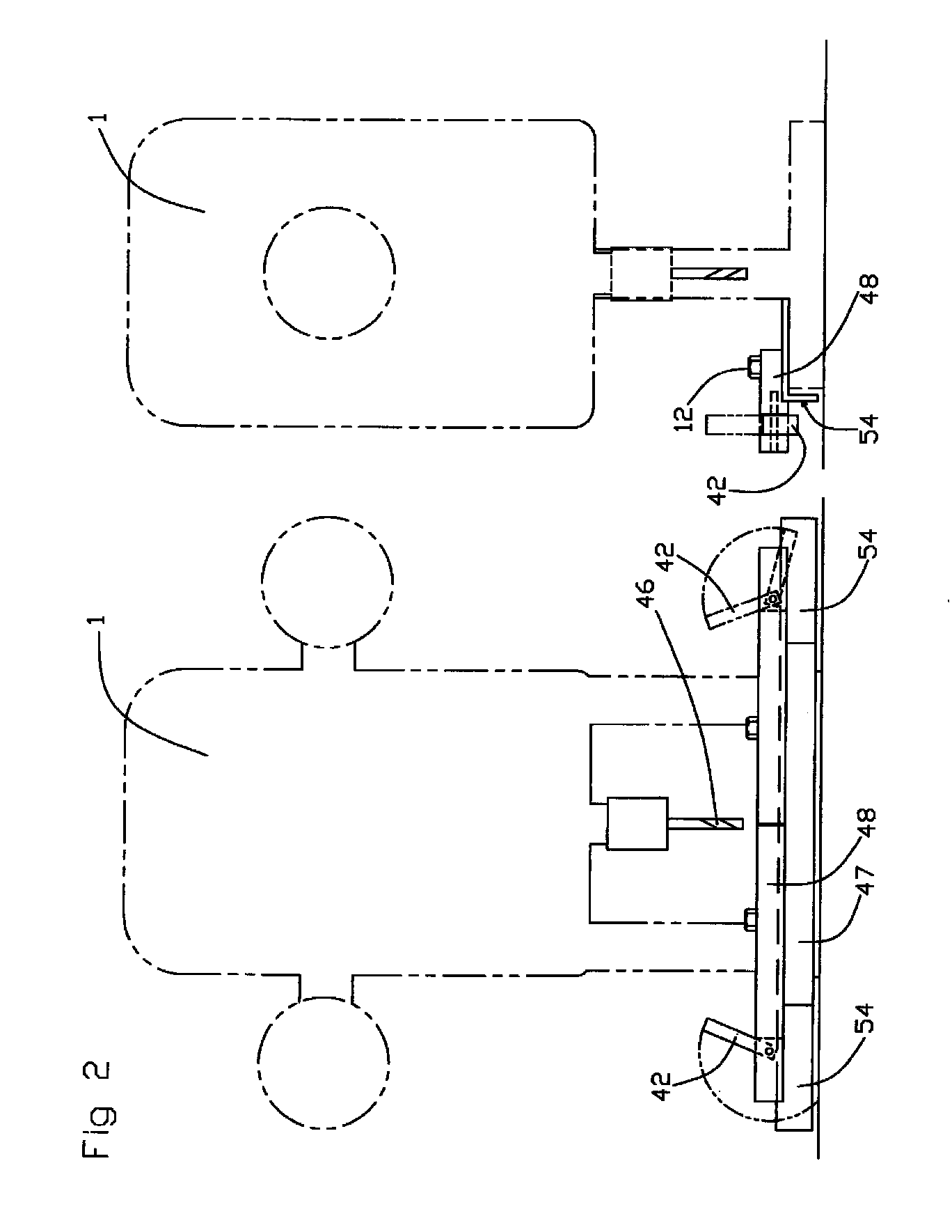
[0042]A plunge router 1 positioned by means of a router guide assembly 2 in conjunction with a guide rail 3 registered to a work holding fixture 4 is used to drill holes in work pieces which in most cases would be cabinet panels. Several standard panel (work piece) sizes and configurations are shown in the various drawing figures, and since all standard panels can be drilled in the manner described...


PUM

PropertyMeasurementUnit
Temperatureaaaaaaaaaa
Lengthaaaaaaaaaa
Timeaaaaaaaaaa

Abstract

A panel face drilling system using a plunge router wherein an attached guide assembly in conjunction with a guide rail registered to a dual position work holding fixture provides tool guiding means to repeatably drill hole patterns within an array of perpendicular columns and rows. The column and row positions are fixed in relation to the work holding fixture. Nonstandard hole positions are obtainable through use of spacers. The work holding fixture is configured to allow loading of two work pieces at a time each to be aligned against a fence, positioned against a stop, constrained by a resilient clamping means, ready for drilling. By referencing the hole position number sets marked on the tool guiding means one can quickly drill required holes in one panel and then drill a mirror image of that hole pattern in a second panel.

Description

FIELD OF THE INVENTION[0001]This invention relates to an economical small shop system for drilling cabinet or book case side panels for the installation of hinge mounting plates, drawer slide components, and shelf supports. It's adaptable to other industrial applications where a hole pattern or an array of points is needed on an essentially flat surface.CROSS REFERENCE TO RELATED INVENTIONS[0002]Not applicable.STATEMENT OF FEDERALLY SPONSORED RESEARCH / DEVELOPMENT[0003]Not applicable.NAMES OF PARTIES TO A JOINT RESEARCH AGREEMENT[0004]Not applicable.REFERENCE TO A “SEQUENCE LISTING”[0005]Not applicable.BACKGROUND OF THE INVENTION[0006]Cabinets and furniture manufactured today in the U.S. for hospitals and medical facilities, business offices, laboratories, many other commercial entities, and increasingly residential kitchens, are often made in the frameless style. These cabinets are simply boxes made from flat panel material such as edgebanded melamine faced particleboard, high press...

Claims


Application Information

Patent Timeline
IPC IPC(8): B23B47/28
CPCB23B47/287Y10T408/56245Y10T408/567Y10T408/563
Inventor SCHMITT, ARTHUR REX
Owner SCHMITT ARTHUR REX
Why Eureka
Try Eureka