Rotational atherectomy system with enhanced distal protection capability and method of use

a technology of atherectomy and distal protection, which is applied in the field of rotational atherectomy system with enhanced distal protection capability, can solve the problems of difficult manufacturing on a commercial scale, complicated construction, and inability to prevent the migration of very small embolic particles

Inactive Publication Date: 2013-06-18
CARDIOFLOW
View PDF16 Cites 39 Cited by
  • Summary
  • Abstract
  • Description
  • Claims
  • Application Information

AI Technical Summary

Benefits of technology

[0030]The present invention seeks to provide a rotational atherectomy system with distal embolic protection which includes a separate drainage catheter and whic

Problems solved by technology

Potentially life-threatening complications which may be caused by the embolic particles produced during the rotational atherectomy procedure prevent use of the above described rotational atherectomy devices for treatment of stenotic lesions in the carotid arteries.
These devices are designed to prevent migration of embolic particles larger than 100 microns and cannot prevent migration of very small embolic particles produced during rotational atherectomy procedure.
The rotational atherectomy device known from U.S. Pat. No. 5,681,336 (to Clement et al.) has a complicated construction and is difficult

Method used


Image

  • Rotational atherectomy system with enhanced distal protection capability and method of use
  • Rotational atherectomy system with enhanced distal protection capability and method of use
  • Rotational atherectomy system with enhanced distal protection capability and method of use

Examples


first embodiment

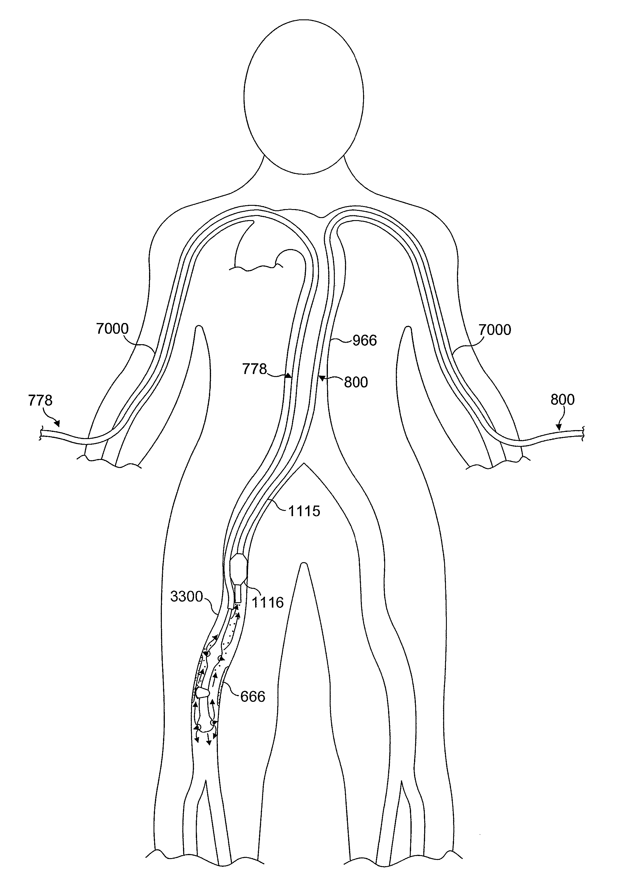
[0083]FIG. 17 illustrates a rotational atherectomy system with enhanced distal embolic protection capability of the present invention, the rotational atherectomy system comprising a rotational atherectomy device with counterweights and a separate drainage catheter, the retrograde flowing fluid being aspirated into the separate drainage catheter, both the rotational atherectomy device 777 and the drainage catheter 800 being shown inserted through separate openings located in the femoral arteries 900 of the patient and meeting in the aorta 966, the drainage catheter 800 extending into the common carotid artery 999 while the rotational atherectomy device 777 passes through the common carotid artery and extends further into the treated internal carotid artery 1500. FIG. 17 illustrates that the openings in the wall of the distal fluid inflatable counterweight of the device are located such that pressurized fluid flowing through the openings forms a fluid bearing between the wall of the f...

second embodiment

[0094]FIG. 23 illustrates the rotational atherectomy system with enhanced distal protection capability. The system of FIG. 23 is similar to the system of FIG. 17 except that the rotational atherectomy device 778 of FIG. 23, instead of counterweights, has support elements having centres of mass lying along the rotational (longitudinal) axis of the drive shaft of the device;

[0095]FIG. 23A is a cross-sectional view of the drainage catheter 800 taken along the line A-A shown in FIG. 23;

[0096]FIG. 24 is an enlarged view of the rotational atherectomy system shown in FIG. 23. FIG. 24 illustrates that the openings in the walls of the distal fluid inflatable support elements of the rotational atherectomy device are located such that pressurized fluid flowing through the openings form fluid bearings between the walls of the fluid inflated support elements and a wall of the treated vessel. FIG. 24 shows that an occlusion balloon 1116 is mounted to a catheter shaft 1115 of the drainage catheter...

fourth embodiment

[0109]FIG. 34 illustrates the rotational atherectomy system with enhanced distal protection capability. The system of FIG. 34 is similar to the system of FIG. 33 except that it includes an external occlusion cuff 4400. FIG. 34 shows that tibial arteries and the most distal segment of the popliteal artery have been occluded by an inflated external occlusion cuff 4400. FIG. 34 illustrates any embolic particles EP abraded by the atherectomy device and not immediately evacuated through the drainage catheter 800 accumulate distal to the site of the treated stenotic area but proximal to a point at which the inflated occlusion cuff has compressed the treated vessel or its distal branches.

[0110]FIG. 35 shows that the occlusion balloon 1116 of the drainage catheter 800 shown in FIG. 34, has been deflated and the drainage catheter 800 has subsequently been advanced sufficiently close to the embolic particles EP accumulated proximal to the segment of the artery occluded by the external occlusi...


PUM


Abstract

An atherectomy system for removing a stenotic lesion from within a vessel of a patient is disclosed. The system comprising an atherectomy device for reducing the lesion and a separate elongate drainage catheter for evacuating from the treated vessel embolic particles released into the vessel from the stenotic lesion during its reduction by the atherectomy device during an atherectomy procedure. The atherectomy device and the separate elongate drainage catheter are each configured for introduction into the patent's vasculature though separate openings in at least one peripheral artery of the patient.

Description

CROSS-REFERENCE TO RELATED APPLICATIONS[0001]This application is a national phase application based on PCT / EP2008 / 065986, filed Nov. 21, 2008, the content of which is incorporated herein by reference, and claims priority of GB Patent Application No. 0722990.9, filed Nov. 23, 2007, the content of which is incorporated by herein by reference.BACKGROUND OF THE INVENTION[0002]1. Field[0003]The present invention relates to a rotational atherectomy system for removing a stenotic lesion from within a vessel of a patient. More specifically, the invention relates to a rotational atherectomy system with enhanced distal protection capability for removing or reducing stenotic lesion in a human artery by rotating an abrasive element within the artery to partially or completely ablate the stenotic lesion and simultaneously remove out of the patient's body abraded particles (embolic particles or debris) released into the treated artery during the rotational athererctomy procedure. It should be und...

Claims


Application Information

Patent Timeline
IPC IPC(8): A61B17/22
CPCA61B17/135A61B17/22A61B17/3207A61B17/320758A61B2017/22067
Inventor SHTURMAN, LEONID
Owner CARDIOFLOW
Why Eureka
Try Eureka