
Apparatus for registration of photons and ionizing particles with simultaneous directional definition, for each photon or ionizing particle, of a point of origin in a fluid-filled conduit

a technology of ionizing particles and detection apparatus, which is applied in the direction of radiation intensity measurement, instruments, x/gamma/cosmic radiation measurement, etc., can solve the problems of not being well suited for maximum collection of inflowing photons, and achieve the effect of increasing the efficiency of capturing and detecting photons, increasing flexibility, and accelerating the speed of operation

Active Publication Date: 2013-06-18
VISURAY TECH
View PDF7 Cites 3 Cited by
  • Summary
  • Abstract
  • Description
  • Claims
  • Application Information

AI Technical Summary

Benefits of technology

The invention offers an apparatus that makes capturing and detecting photons more efficient, which offers users flexibility either by performing operations faster without sacrificing quality or with the same time consumption but increasing data acquisition and accuracy of measuring results. The apparatus enables directional definition of the point of origin of incident radiation in a borehole, creating a true 360-degree picture of the wellbore and the surrounding geological materials. The detection apparatus exhibits greater efficiency in collecting and registering photons, and can be used as well-logging detectors.

Problems solved by technology

Even though scintillators are in general use, the scintillator has physical properties that do not make it well suited for maximum collection of inflowing photons.

Method used


Image

  • Apparatus for registration of photons and ionizing particles with simultaneous directional definition, for each photon or ionizing particle, of a point of origin in a fluid-filled conduit
  • Apparatus for registration of photons and ionizing particles with simultaneous directional definition, for each photon or ionizing particle, of a point of origin in a fluid-filled conduit
  • Apparatus for registration of photons and ionizing particles with simultaneous directional definition, for each photon or ionizing particle, of a point of origin in a fluid-filled conduit

Examples


Embodiment Construction

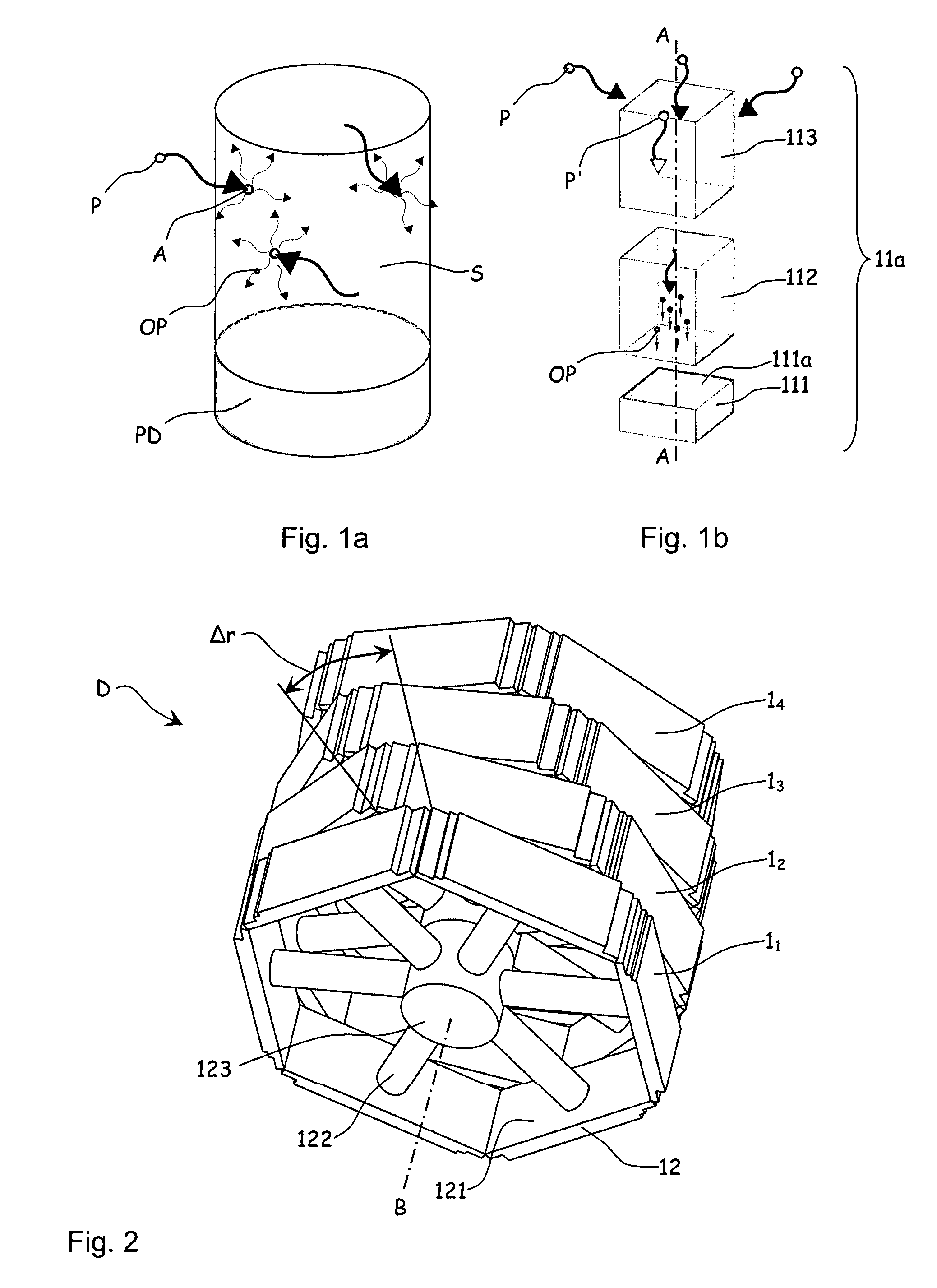
[0034]In FIG. 1a which shows schematically a scintillator S in which, according to the prior art, incident photons P having random directions of motion (indicated by large arrows) affect atoms in the scintillator S so that a great many optical photons OP with random directions of motion (indicated by small arrows) are formed. Some optical photons OP reach a receiving surface on a photodiode or photomultiplier tube PD and generate a registration, whereas the other optical photons OP are lost to the surroundings.

[0035]In FIG. 1b is shown schematically an exploded detecting unit 11a provided with an electronic charge reader 111, a scintillator 112 and a collimator cell 113 only letting photons P through that have a direction of motion that coincides with a longitudinal axis direction A of the collimator cell 113. Photons P′ that have been collimated affect the scintillator material 112, for example cadmium telluride, across which an electric field (not shown) has been set up, and a cas...


PUM


Abstract

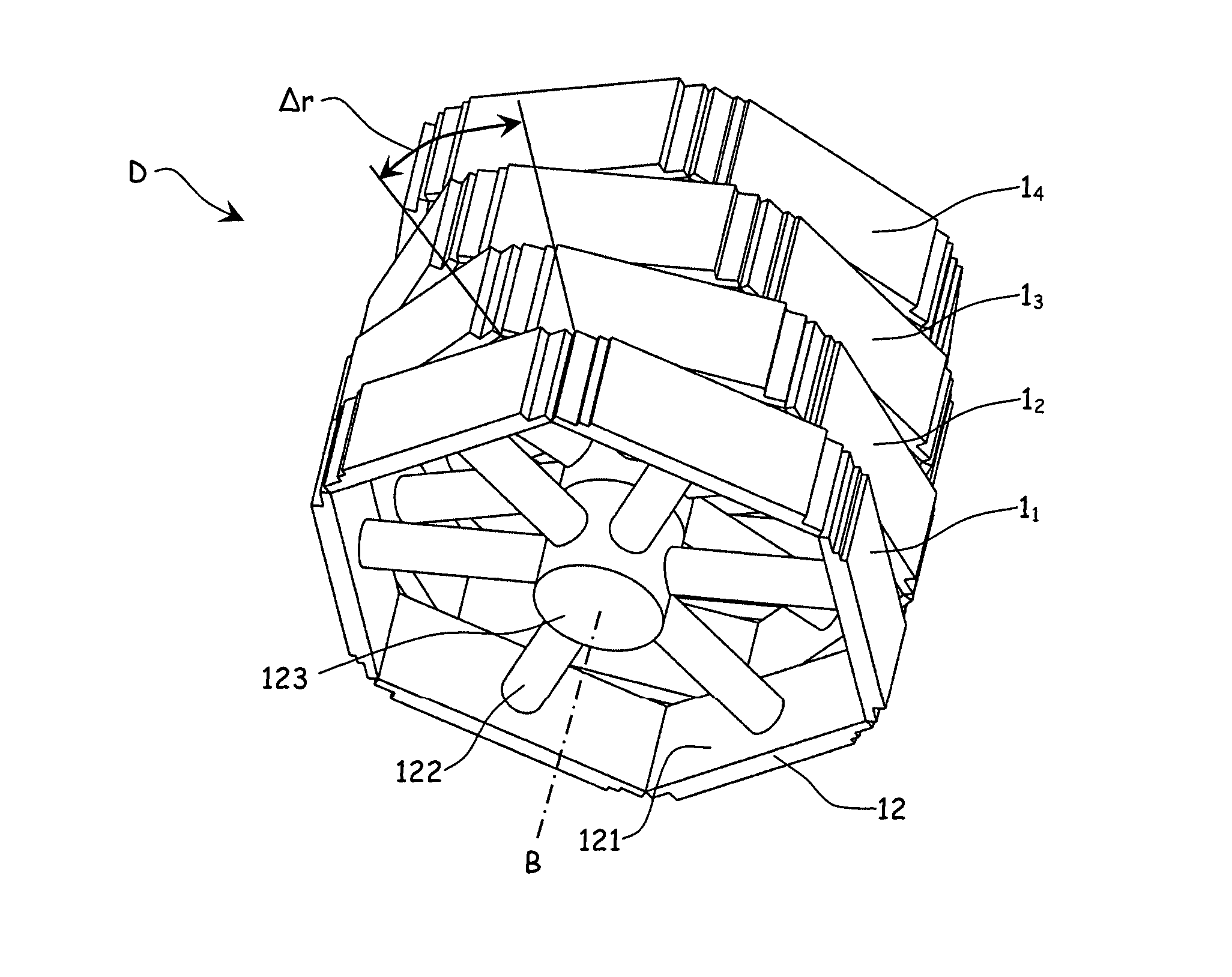
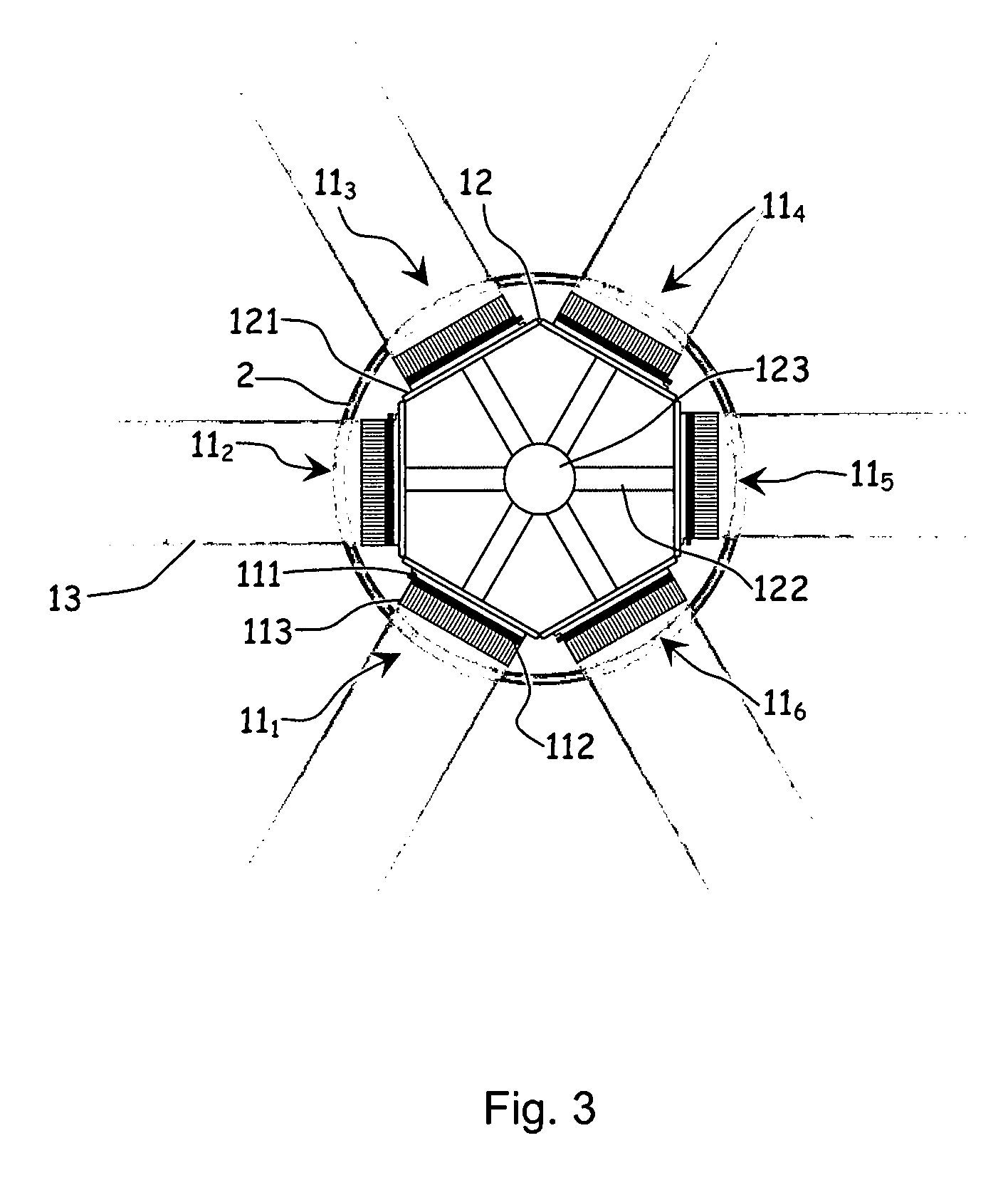
A detection apparatus (D) for photons or ionizing particles (P) is described, in which a detector system (11) is provided with several detecting units (11a), each including a scintillator (112) connected to a reader surface (111a) on an electronic charge reader (111), the scintillator (112) being arranged to generate cellular charges on the reader surface (111a) when capturing the photons or the ionizing particles (P), there being a collimator (113) arranged, connected to the scintillator (112) opposite the electronic charge reader (111), the collimator (113) being arranged to capture photons or ionizing particles (P′) exhibiting a direction of motion coinciding with a longitudinal axis (A) of the collimator (113), and to reject photons or ionizing particles (P′) exhibiting a direction of motion deviating from the direction of the longitudinal axis (A) of the collimator (113).

Description

CROSS REFERENCE TO RELATED APPLICATIONS[0001]The present application is a 35 U.S.C. §371 National Phase conversion of PCT / NO2011 / 000097, filed Mar. 22, 2011, which claims benefit of Norwegian Application No. 20100440, filed Mar. 25, 2010, the disclosure of which is incorporated herein by reference. The PCT International Application was published in the English language.TECHNICAL FIELD OF THE INVENTION[0002]The invention relates to a detection apparatus for photons or ionizing particles, in which a detector system is provided with several detecting units, each including a scintillator connected to a reader surface on an electronic charge reader, the scintillator being arranged to generate cellular charges on the reader surface when capturing the photons or the ionizing particles, more particularly by a collimator being arranged, connected to the scintillator opposite the electronic charge reader, the collimator being arranged to capture photons or ionizing particles exhibiting a dire...

Claims


Application Information

Patent Timeline
Patent Type & Authority Patents(United States)
IPC IPC(8): G01V5/04G01T1/20
CPCG01V5/04G01T1/2907G01T1/2921G01V5/12
Inventor TEAGUE, PHIL
Owner VISURAY TECH
Learn More